What is it?
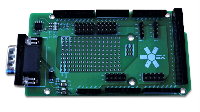
Picture 1. Shield for Arduino
Any spacecraft contains in its composition the target equipment that ensures the fulfillment of its main task. This equipment, for which a given spacecraft is created or launched, is called a spacecraft payload.
The designer contains modules that are often used as a payload, for example, a camera. However, sometimes it is necessary to expand the functionality of the constructor by using non-standard modules. The ability to easily create such modules is provided by the open Arduino platform, which integrates into the on-board information network of the designer. The provided expansion module uses an Arduino Mega 2560 board based on the ATmega2560 chip. The information exchange between the Arduino microcontroller and the BCC takes place using an expansion board (so-called shield), which is installed on a board with a microcontroller. The expansion board contains a connector for connecting to the cable network via a standard loop of the RS-485 interface designer.
Organization of information exchange
The Arduino board has a serial UART port for communication with other devices. Digital input/output ports 0(RX) and 1(TX), as well as a USB port, are used for data exchange. The expansion board also has RX and TX connectors, to which the device's information network cable is connected. To communicate between the microcontroller on the Arduino board and the BCC, it is necessary to connect the connectors of the RX bus and the board itself, and use the Serial set of functions for Arduino.
The principle of the network
A communication protocol is used to organize information exchange, which ensures accurate and unambiguous transmission of information. When accessing any device, the BCC sends a request over the bus, which is perceived by all connected devices, but only the called device responds to it. The index of the called device is specified in the request. When accessing the Arduino board, this protocol is also used, the board has its own index attached. The request, which is perceived by the board from the BCC, is a sequence of some characters in the ASCII table format. To ensure interaction between the BCC and the microcontroller, the microcontroller must read the string of characters sent by the BCC from the bus, decrypt it, and perform the specified actions. The sequence of actions of the microcontroller when receiving a certain sequence of characters from the BCC is prescribed in the firmware program of the board. The sequence that the BCC sends to the bus, and which is perceived by Arduino for decryption and execution, is written in the program that is sent to the BCC using the web interface.
You can download the test cases here:
- led_test is a sketch for the Arduino Mega 2560, which allows you to turn on and off the diode on the 11th pin on command from the BCC, a sketch for the BCC, and an archive for the BCC firmware via the web interface.
An integrated development environment is used to work with the Arduino board - Arduino IDE. You can download it from the official website of the Arduino platform developer company.
Standard developer software is used to work with BCC programs: download developer software