About the complex
Purpose
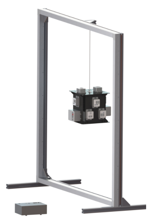
The OrbiCraft constructor (Picture 1), together with the Terra space environment simulator complex, is a semi-natural simulation complex designed to teach schoolchildren and students the basics of developing, designing, assembling, testing and operating a spacecraft.
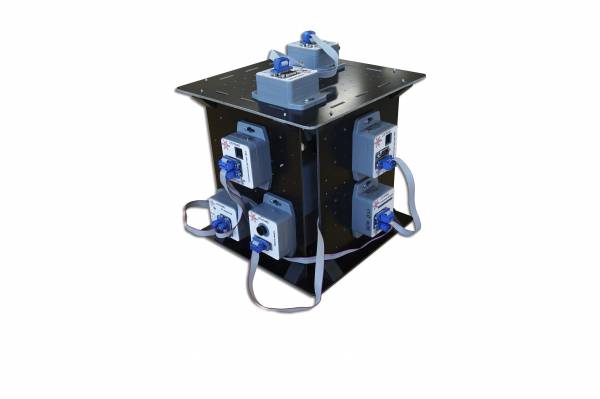
Picture 1. OrbiCraft
The main feature: instead of developing individual systems and delving into their detailed design, the complex as a whole and the designer in particular allows you to focus on the system design of the spacecraft as a whole and quickly obtain a result - a working prototype.
Composition
The set of the complex includes:
- A set of modules for assembling functional satellite layouts - OrbiCraft constructor;
- The Terra Space Environment Simulator complex.
Picture 2. OrbiCraft Kit
A functional satellite layout (an object assembled from the OrbiCraft constructor) may contain (Picture 3):
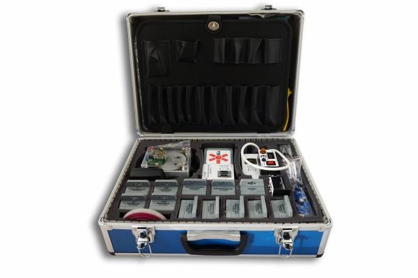
Picture 3. Composition of the set
- payload - a camera for taking pictures of the space around you;
- central on-board computer based on Raspberry Pi;
- power supply system, including battery, power management unit;
- a system for transmitting commands and collecting telemetry, including a radio transmitter on board and on the Ground;
- an orientation and stabilization system, including solar sensors, a magnetometer and an angular velocity sensor, as well as a flywheel motor;
- Software;
- a set of manuals and instructions for the assembly and use of the designer as part of laboratory equipment.
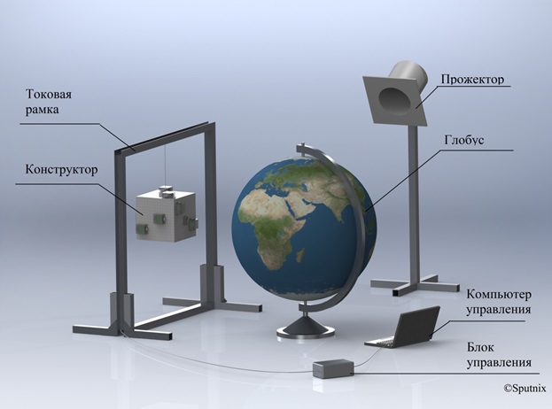
The Terra Space Environment Simulator complex includes (Picture 4):

Picture 4. Composition of the Terra Space Environment Simulator Complex
- rotating globe - simulator of the Earth's surface, simulating the kinematics of the translational motion of a satellite in Earth orbit
- a searchlight - a simulator of the Sun, providing a stream of solar radiation for the operation of solar sensors
- a current frame - a geomagnetic field simulator for the operation of the on-board orientation system
- a special string suspension (thread) that ensures the movement of the satellite relative to the center of mass
- "Mission Control Center", which includes a ground-based transceiver, special software for a personal computer that functionally simulates the operation of a real spacecraft Flight Control Center
Earth Simulator
The Earth simulator is an Earth globe (Picture 5), which provides:
- a geometrically scaled appearance of the Earth, visible from a satellite, with a diameter of 130 cm.
- the kinematics of satellite movement along the subsatellite path along the equatorial orbit - either in real time or using reasonable scaling (acceleration, time dilation), the conditions for shooting certain areas of the surface are similar and in the same terms as shooting the real Earth's surface by ERS satellites (time, orbital parameters, point coordinates, region coordinates);
- conditions of communication with the "ground" (ground measuring points – NPCs) via telemetry and telecommand radio lines, when the ground point is in the zone of geometric radio visibility of the board, the LEDs of the corresponding "ground station" turn on;
- conditions for transmitting data "to the ground" via a high-speed communication channel when the ground station is in the zone of geometric radio visibility of the board.

Picture 5. Earth Simulator
The satellite "flies in near-Earth orbit", and in fact - hangs on a thread in a simulated "geomagnetic" field (inside the current frame) and rotates horizontally on the thread - either freely or under the action of an on-board control system programmed by the user - while the globe of the Earth in front of it rotates evenly, simulating the movement of the device in an equatorial orbit. The area of the globe surface required for shooting in the area of the equator of the globe sooner or later turns out to be in front of a hung device, and the task of the satellite control system is to orient and stabilize the satellite on the suspension by this moment, directing the camera's field of view with the necessary accuracy to the area of interest, remove it and then transfer the shooting data "to the Ground" to the user, accompanying this the ability to orient the laser pointer to the required "ground" reception point.
The Globe is controlled via the USB port of a PC, whose tasks include controlling the rotation of the globe, as well as managing a network of "ground" (on the surface of the globe) telemetry reception and processing centers (NIPS), as well as "surface" centers for receiving high-speed information. These centers are located on the surface of the "Earth" in pre-known, predetermined and time-invariant geographical points.
The conditions of communication with the "Earth" via telemetry and telecommand radio lines are simulated by calculating when one or another NPC on the surface of the globe is in the zone of geometric radio visibility with a side suspended on a string, and issuing the appropriate command to turn on or off the radio receiver of this ground station. After switching on, the ground station is in the telemetry data reception mode by default.
Conditions for transmitting data from the board to the "Earth" (photodetector on the surface of the globe) over a high-speed communication channel, they are simulated using the illumination and holding of the pointer of a given marker on the surface of a rotating globe by an on-board laser beam. The fact that the photodiode is illuminated on the surface of the globe for a given time interval is a sign of the normal orientation of the "board" to the "Earth", after which data from the board is transmitted over a regular Wi-Fi channel all the time while the HF transmitter LED illuminates the necessary marker.
The main characteristics of the globe:
- diameter 130 cm.
- the weight of the entire simulator (the globe and the drive with the control system hidden inside) is 40 kg,
- the mass of the globe is 20 kg, the material of the globe is durable fiberglass,
- Good contrast coverage of the globe,
- a map with a view of the Earth from space and a grid of parallels and meridians
- vertical axis of rotation of the globe,
- the rotation speed of the globe is 0.2 rpm,
- all drives, electronics, etc. are located inside the globe,
- The globe is connected to a 220V outlet and to the USB port of the control PC.
Characteristics of the globe control system:
- single-axis electric drive;
- Drive driver and driver control board;
- connecting to a computer via the USB interface;
- a control system for "ground" telemetry points, as well as a photodiode for detecting the light of a laser pointer "board".
All geometric parameters of the globe, kinematic parameters of its rotation are consistent with the capabilities of the dynamic system of the onboard control system of the satellite layout (speed, accuracy, number of degrees of freedom, continuous operation time)], as well as with the capabilities of the on-board payload (field of view, exposure time, illumination conditions, data transfer rate) used as part of the layout to obtain special information.
Sun Simulator
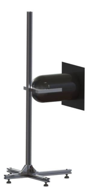
Picture 6. Sun Simulator
The Sun simulator (Picture 6) is a light source that provides a beam of light, similar in a number of characteristics to the solar one, in order to influence the orientation system of the layout, as well as the conditions for shooting areas of the globe with a camera installed as part of the satellite layout.
The main parameters of the simulator:
- the non-parallelism of the beam is not worse than 12 degrees;
- the radiation spectrum is as close as possible to the solar one;
- the diameter of the light beam concentrating 90% of the power, no more than 20 cm;
- the power of visible radiation is close to Solar 1367 W/m2 at a distance of at least 0.2 m from the light source;
- eye safety (protection in the form of glasses);
- during the experiment, the simulator is stationary, and can be easily moved by one person to any distance between experiments;
- powered by a regular 220 V mains;
- the presence of a mounting system (tripod), which allows for smooth adjustment of the light source in height (from 0.5 to 1.5 m), in the angle of inclination to the horizon (-60..60 degrees).
The Sun simulator must be turned on by the user before starting the experiment and turned off after conducting the experiment manually using a conventional switch.
Earth's magnetic field simulator
The Earth's magnetic field simulator (Picture 7) is a closed solenoid (Helmholtz ring) designed to create a controlled magnitude of magnetic flux directed through its vertically mounted plane (working plane). Such a frame plays the role of a simplified uniaxial simulator of the Earth's magnetic field.
Picture 7. Earth's magnetic field simulator
The current frame is installed on the floor and provides the possibility of placing the OrbiCraft constructor on the thread so that its center of mass is placed in the working plane – the equatorial plane of the globe, at a height of about 80 cm from the floor, and its unlimited free rotation is ensured.
The main characteristics of the solenoid:
- The uniformity zone (5%, 1 degree) coincides with the size of the constructor;
- Material: aluminum frame, copper conductor;
- Dimensions: provide free rotation of the layout inside it on a string with the possibility of height adjustment by +- 5 cm;
- Continuous operation time at full power: at least 4 hours;
- Supply voltage: no more than 27 V;
- Safe for laboratory use.
The principle of operation
The functional layout of the "satellite", assembled from a set and programmed by the user, is suspended on a thread, after which it is slightly twisted on the thread and released, allowing the layout to make flat torsional oscillatory movements.
Depending on the task being solved by the satellite, a set of orientation sensors, the composition and layout of the main systems and payload, as well as the firmware, the satellite must stabilize its rotation on the suspension (stop), then turn to the "Earth" with one of its side surfaces and take a photo of a given section of the running "earth" surface.
The variability of tasks is determined by different success criteria – maximum performance, various guidance algorithms, guidance accuracy, simplicity and speed of implementation, a minimum of onboard devices used in the layout, a maximum of information transmitted from the board, etc.
The layout of the stand
The general view of the assembled complex and the classic installation scheme of the Terra space environment simulator complex and the OrbiCraft constructor in its composition are shown in Figure 8.
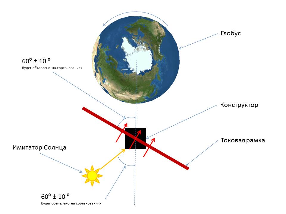
Picture 8. Installation diagram of the Terra space environment simulator complex and the OrbiCraft designer
Sputnix LLC has the right to refuse warranty service of the equipment in case of detection of signs of violation of storage, transportation and operation conditions, as well as in case of user intervention inside the units of the equipment that are not intended for disassembly by the user.