Description of the Zavitok complex The
complex provides the possibility of two-way communication with small spacecraft. In addition to all the functionality of the complex "Vyunok" in terms of data reception, "Zavitok" also allows you to send control commands to the satellite in accordance with the regulations of amateur radio communication, and also provides much better reception at low altitude of the satellite above the horizon.
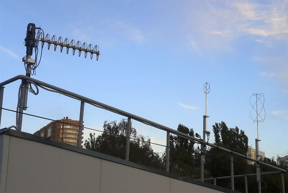
Picture 1. The complex "Zavitok" on the roof of the building
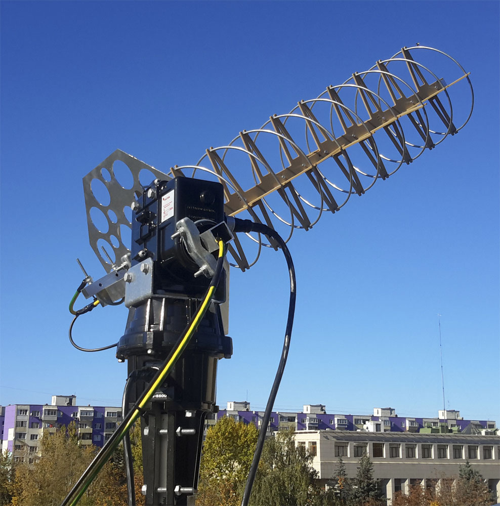
Picture 2. Satellite reception and control station "Zavitok"
"Zavitok" is based on SDR technology (software-defined radio technology), that is, at least the basic demodulation operations are performed programmatically. The complex provides calculation of the spacecraft position in the sky, antenna rotation to the calculated point, calculation of the necessary frequency shift to compensate for the Doppler effect, as well as automatic frequency adjustment during reception and transmission taking into account this shift.
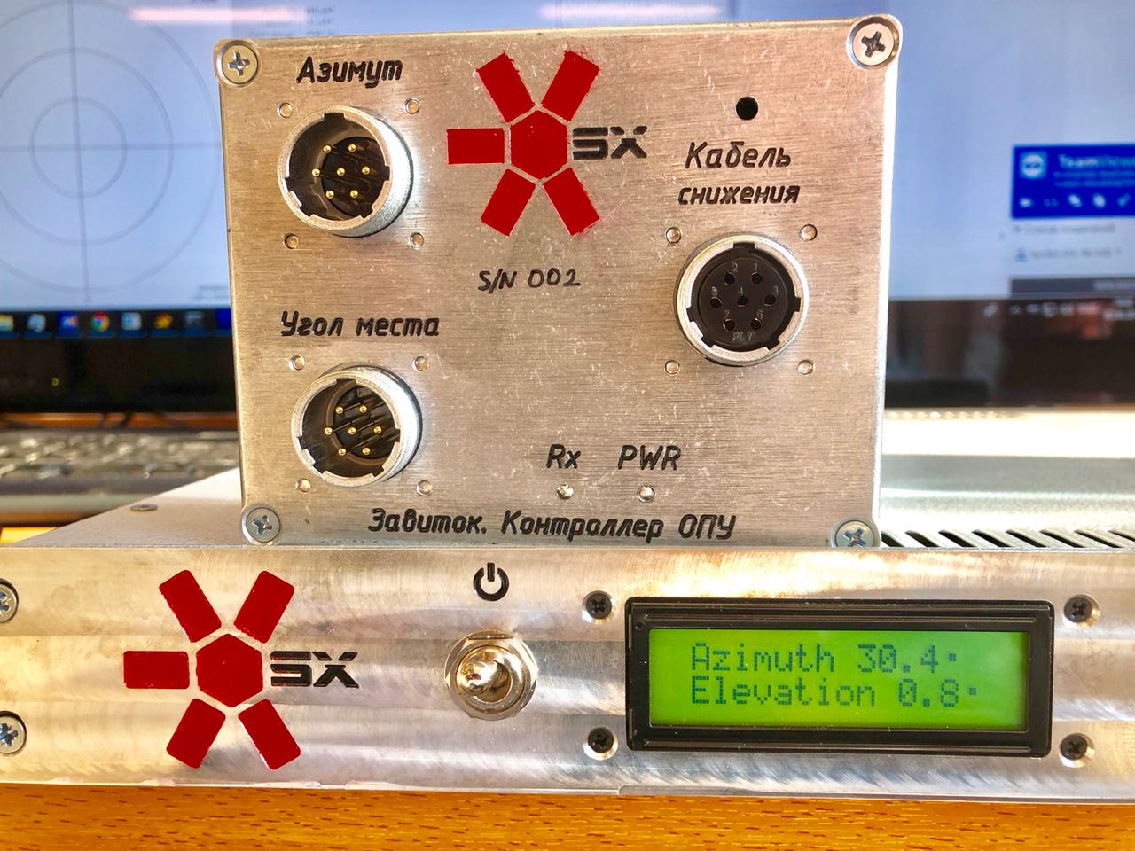
Picture 3. Rotary support Device Controller (OPU)
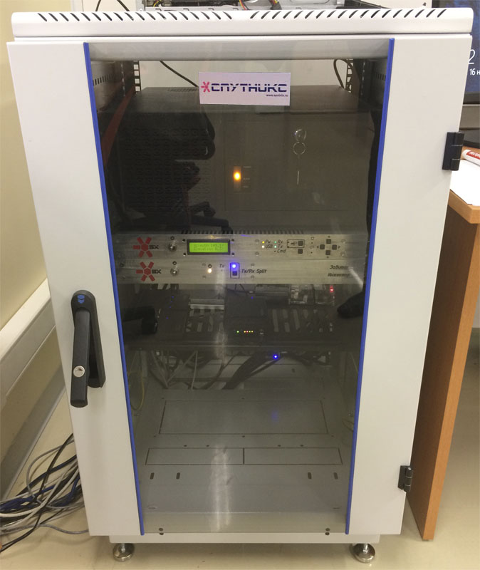
Picture 4. Software-controlled current source (PUIT)
The complex includes an antenna with a high gain on a pivoting support device, as well as observation antennas with a wide directional pattern, similar to those used in the "Bindweed" complex.
The complex is also equipped with an external web camera to monitor the operation of the rotary antenna.
The complex can be divided into two parts:
- antenna complex;
- radio engineering complex.
Antenna complex
The antenna complex consists of two fixed quadrifilar antennas of 136-146 MHz, 435-438 MHz, a spiral antenna of 430-440 MHz with a two-axis rotary device.

Picture 5. The scheme of the complex "Zavitok"
Fixed quadrifillary antennas can be used to receive images from NOAA and Meteor meteorological spacecraft, receive telemetry from spacecraft operating in the frequency range of 136-146 MHz, as well as receive telemetry from spacecraft operating in the frequency range of 430-440 MHz, with a location angle of more than 20...30 degrees, but without the need to point the spacecraft antenna at the sky, which is convenient in the absence of data on the orbital parameters of the spacecraft and when working with several spacecraft at the same time. The antennas are used in conjunction with a diplexer amplifier, which amplifies the received signals to compensate for losses in the reduction cable and provides mixing of signals in two bands into one cable.
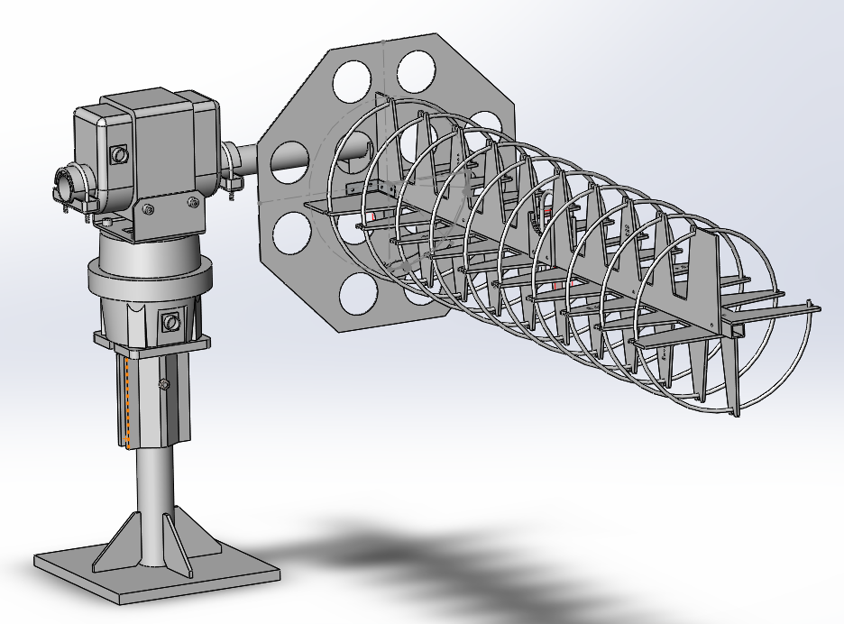
The third antenna of the complex is directional, has high gain, so that in a typical case it can work with spacecraft in the range of 430...440 MHz from angles of about 5 °. This antenna is mounted on a two-axis pivoting device that allows you to point it at any point in the sky. Directional is used with a combined amplifier, which includes a low-noise amplifier with a filter and a power amplifier, as well as an automatic (VOX) receive-transmit switching circuit. Installing a power amplifier in close proximity to the antenna allows, observing the power limit of the transmitter of an amateur radio station of the third category, to obtain an EIM (EIRP) high enough for confident communication with spacecraft.
Fixed antenna of the 136-146 MHz band
The operating frequency for reception is 136-146 MHz The nominal gain of a non-directional antenna at the zenith is 3-4 dBi
Picture 6. Fixed antenna of the 136-146 MHz band
Fixed antenna of the 430-440 MHz band
- The operating frequency for reception is 430-440 MHz
- Nominal gain of a non-directional antenna at the zenith is 3-4 dBi
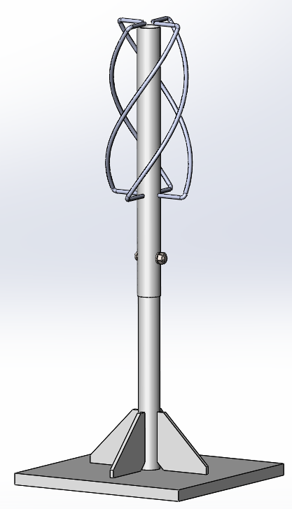
Picture 7. Fixed antenna of the 430-440 MHz band
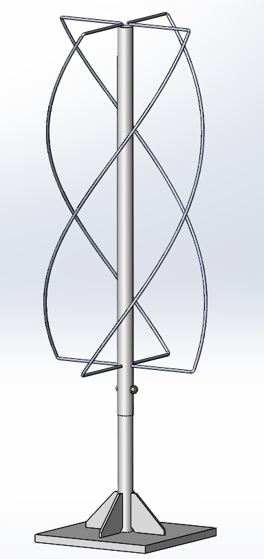
Directional antenna of the 430-440 MHz band
- The operating frequency for reception is 430-440 MHz
- Nominal gain of the non-directional antenna is 11 dBi
- The width of the radiation pattern at the level is 3dB ±20º
Picture 8. Directional antenna of the 430-440 MHz band
Radio engineering complex
The basis of the radio engineering complex is a workstation with software deployed on it. A LimeSDR or HackRF SDR transceiver and, if necessary, an RTL-SDR SDR receiver are connected to it.
Communication of SDR devices with antennas is carried out through an injector, which supplies phantom power to the cable for antenna complex devices, amplifies the transmitter signal, and serves as a patch panel for switching various station configurations, allowing you to connect any devices to any antennas.
The OPU interface controls the rotary support device according to commands from the workstation via the USB interface and transmits the position of the antenna in the opposite direction. Direct manual control is also provided (turns, installation in a stormy position, emergency stop). Raspberry Pi makes it easy to integrate the station into the international SatNOGS network. A network switch provides interconnection of devices over an Ethernet interface and access to the outside world.
The output power of the transmitter is 10 W (40 dBm)