Working with the Terra complex
Mission Control Center
Mission Control Assignment (FCC)
The FCS works on a "ground-based" computer and provides the necessary functionality for receiving and displaying data from Orbicraft (from a "satellite") - both on the operation of on-board telemetry systems and data from the payload. The "unknown" installations are an RF receiver and a VHF receiver, which are connected to a computer via USB-RS485.
In the case of using the Terra space environment simulator complex, an Earth simulator (globe) and a control unit for an Earth magnetic field simulator (magnetic frame) are connected to the computer.
Installation of FCC software and USB-RS485 wireless cable
Installing the driver for USB-RS485:
Download the driver for the USB cable from the "Software" section (/docs/orbicraft/instructions for working with orbicraft/required software);
Open the download archive ch341ser.zip;
Arrested SETUP.EXE and wait for an offer from the experienced drayver company (photo 1):
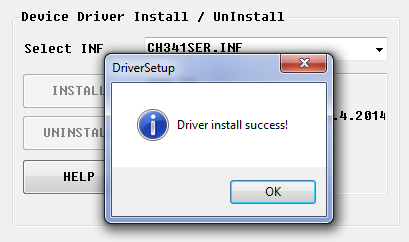
Figure 1. Installing the driver
Click OK;
Close the driver installation window.
Registration With The FCC
- Check out the FCC from the section FCC Flight Management with the [Optional Software] pages(/docs/orbicraft/instructions for working with orbicraft/required software);
- Rigid jump-like movement in space **C:** (corendisca C);
- Log in to the app GroundControl(version);
- Run GroundControl_(version).exe.
:::hint You can also establish a connection with the FCC anywhere else. It is important that the folder location path is written in Latin, without using special characters (!#@, etc.), does not contain spaces and does not start with a digit. :::
What is the FCC?
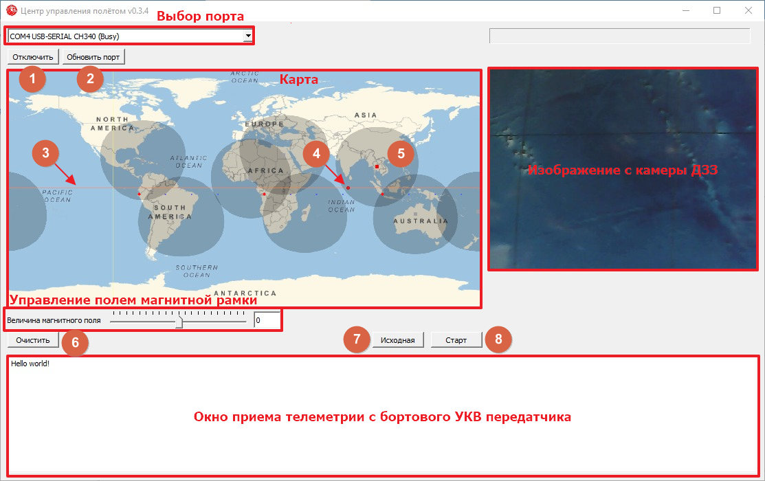
Figure 2. Information About The FCC_
The FCC sees only one window with a view of the field (Figure 2):
- Port selection: After connecting the USB-RS485 cable from the configurator kit to the computer, you need to connect the port USB-SERIAL CH340 for more information;
- Map: This field is used when working with Terra laboratory equipment. The dot (4) indicates a satellite that is moving in orbit (3). The dark fields (5) indicate the areas of operation of ground-based VHF receiving stations, and the red dots indicate stations receiving RF signals;
- Telemetry reception: at the bottom there is a window for displaying telemetry information coming from the on-board VHF Orbicraft transmitter (from "satellite" to "Earth");
- Remote sensing camera image: The images that you will receive from the remote sensing camera will appear in this field.
Getting a picture from the camera
Getting information from a camera that requires working with the FCC program from the [Required Software] section(/docs/orbicraft/instruction_for_working_with_orbicraft/required_software) and using someone else's state, pampered country.
Screenshots may stand out for different versions of the Windows operating system.
Connecting the Camera
Turn on the camera using a special DB-9F "Papa-Papa" camera to the BKU (photo 3):

Figure 3. The Papa-Papa chair
In order to assemble you, you can read [here](/docs/orbicraft/instructions for working with orbicraft/cable network).
Connecting the RF transmitter
Connect the RF transmitter to the Orbicraft constructor network.
:::Advice When the RF channel is working on the constructor, the LED of the RF transmitter emits a light signal, and the sensor on the RF receiver picks it up.
The real RF channel on spacecraft does not use light signals, but operates on the basis of high-frequency radio communication. After all, this app allows users to view video recordings, including DVRs, as well as DVRs connected to a Wi-Fi channel. between the bank and the FTP server, which is configured automatically on the personal computer when the FCC is launched (GroundControl_(version).exe). This approach makes it possible to simulate the process of transmitting images to Earth. :::
:::Advice The RF receiver can be connected to the user's computer using the USB adapter interface included in the kit of the designer. While working with the globe, RF receivers built into the globe can be used. :::
It is mandatory to have an RF transmitter in the designer's network to transmit the image. It is not necessary to use this technique in order to take a picture, since just this picture should have appeared and appeared in the FCC before.
Setting a static IP address
Log in to Control Panel → Network and Internet → Network management and all other equipment (Figure 4):
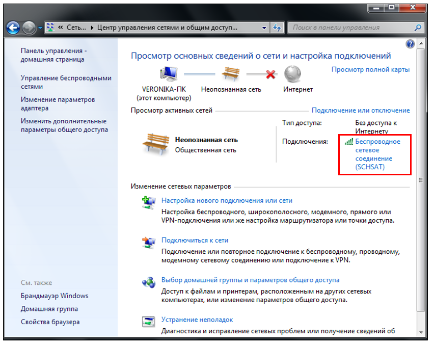
Figure 4. Full control over networks and all other equipment_
Find a Derived network connection (Photo 5):
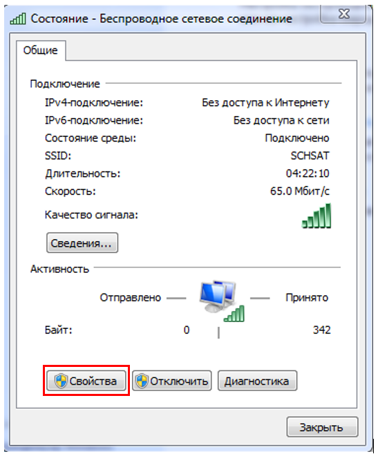
Figure 5. Production network association
Click Link (Figure 6):
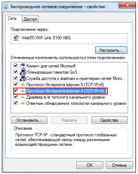
Figure 6. Work
Click On the Embedded Version 4 (TCP/IPv4) screen (Figure 7):
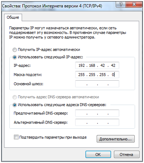
Figure 7. Overview of the internal version 4_
Open immediately after checking the box Use the following IP address:
- specify the IP address 192.168.42.42;
- Click on the empty columns of the Subnet Mask item, the address 255.255.255.0 will automatically appear in them;
- Click OK.
:::Warning After approving the work with the contractor, do you need to mark the settings automatically to "Connect the IP address automatically"? It's just that a standard Wi-Fi connection won't allow it to work! :::
Removing Firewall Windows
Windows Firewall can block access to the Wi-Fi network, so it cannot be disabled.
Click Control Panel → Windows Firewall (Figure 8):
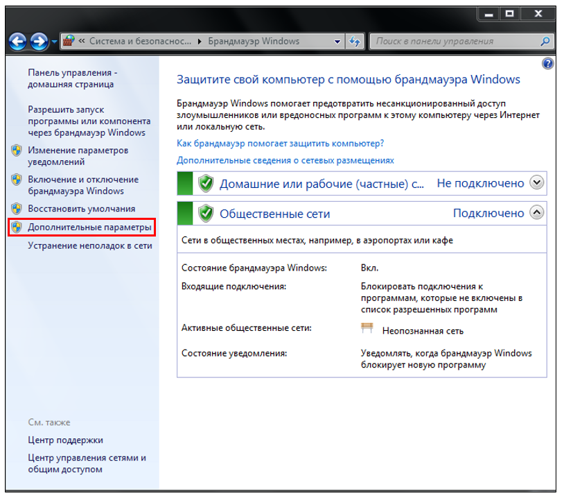
Figure 8. Firewall Windows
Press Additional parameters (Figure 9):
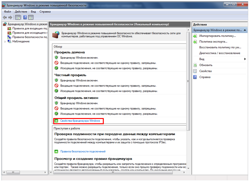
Figure 9. Additional parameters_
Press Windows Firewall Lock (Figure 10):

Figure 10. Windows Firewall System
A window will open containing 4 tabs. In the drop-down list of the Domain Profile tab, in the Firewall Status field, change the Enable state to Disable, repeat the same in the Private Profile and General Profile tabs.
:::Advice You can install the computer after checking the work with the console by turning on the Windows Firewall window and clicking the "Set recommended parameters" button. :::
FCC Launch
Register with the FCC. In order to run FCC (GroundControl_(version).exe), you can read [here](/docs/orbicraft/instructions for working with orbicraft/mcc).
First, the FCC is automatically uploaded via an FTP server in real time. In fact, it is he who takes the picture from the camera. You constantly have to work with only one FTP server for direct access to the recording.
:::Warning Or have you run the FCC (ground-based Control.exe ), you will agree that in this case it is best to stock up on one word ftpdmin. Press constantly on the keyboard Ctrl+Alt+Delete → Task Manager (Task Manager) → Tab Offers.
Figure 11 shows an example where several such processes are running. Therefore, it is necessary and necessary to disable all functions of ftp dmin (select functions and press the button to access), and then stock up on FCC support.
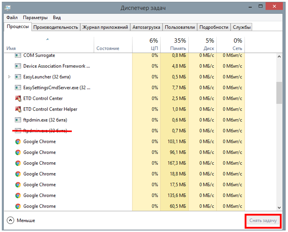
Figure 11. Closed windows_ :::
Launching the program
- Run the program to capture and transfer the image.
In order to create and stock up on the program, you can read [First Knowledge] in it (/docs/orbicraft/lessons/first_program).
The following technical program (which is also presented in the section DZ Camera), allows you to get data on shooting in a row and go to [FCC](/documents/orbicraft/instructions for work withorbicraft/required software). Let's switch to the FCC program (GroundControl(version).exe) connected to the user's computer to access the full image.
Sample code for checking the camera and RF transmitter in C:
``cpp #enable "libschsat.h" // Demonstration of camera capture , control is invalid(void) { int i;
    if (LSS_OK == camera_turn_on()) {
        for (i = 1; i < 10; i++) {
printf("Take a picture #%d\n", i); if (camera_take_photo(i)) { puts("\tFail!"); } } } more { puts("\tFail!"); } printf("Turn on the transmitter #1\n"); if (LSS_OK == transmitter_turn_on(1)) { for (i = 1; i < 10; i++) { printf("Send a photo to #%d\n", i); if (photo transmitter(1, i)) { puts("\tFail!"); } } } more { puts("\tFail!"); } printf("Disable transmitter #1\n"); if (transmitter_turn_off(1)){ puts("\tFail!"); } } ``
Sample code for checking the camera and RF transmitter in Python:
# Program for taking one snapshot and transmitting
it to def control():

#Initialize variables
    num = 1
    frame = 0
    err = 0
    err_transmitter = 0

    #Turn on the camera and transmitter and wait for them to load
camera_turn_on()
transmitter_turn_on(num)
sleep(1)

    # Taking a picture
    err_camera = camera_take_photo(frame)

    if err == 1:
        print 'Camera access error, check the connection', frame

    elif err == 2:
        print 'Camera interface errorr, check the code', frame

    #Passing the snapshot
    err_transmitter = transmitter_transmit_photo(num, frame)

    if err_transmitter == 1:
        print 'Transmition failed'


    #Turning off the devices
    camera_turn_off()
    transmitter_turn_off(num)
The received photos are located in the folder FTP(File Transfer Protocol), which is created automatically in the folder Ground_Control, from which the program GroundControl_(version) is launched.exe. The files can be located in the folders caught and missed, depending on whether the signal hits the RF transmitter: if the signal hits, the data is recorded in the folder caught (received), in case of a weak signal or its absence, the files are considered lost and recorded in the folder missed (missed).
Receiving VHF telemetry
The VHF receiver from the designer simulates the operation of the radio receiving part of a ground station receiving telemetry information over a low-speed VHF channel. Similar receivers are mounted inside the Earth simulator (inside the globe), however, for preliminary testing of work with the satellite, this VHF telemetry receiver with a USB cable for connection is also supplied.
The receiver itself works in conjunction with the FCC software. When telemetry data is transmitted by an on-board radio channel and a connected VHF receiver in a terrestrial network, this data will be automatically received by the terrestrial radio channel and displayed in the telemetry window of the FCC user interface.
The VHF receiver in the OrbiCraft constructor has the number "1" (indicated on the case).
Code for receiving VHF data
Code for receiving VHF data in C:
    #include "libschsat.h"
    /*
    ** Lab 8: UHF transceiver demo.
    */
    void control(void)
    {
        const uint16_t tx_num = 2;
        const uint16_t rx_num = 1;
        const char hello[] = "hello, world!";
        printf("Enable transceiver #%d\n", tx_num);
        transceiver_turn_on(tx_num);
        Sleep(1);
        bus_setup();
        printf("Send data from #%d to #%d\n", tx_num, rx_num);
        if (LSS_OK != transceiver_send(tx_num, rx_num, (uint8_t *) hello, sizeof(hello)))
            puts("Fail!");
        printf("Disable transceiver #%d\n", tx_num);
        transceiver_turn_off(tx_num);
        return;
    }
Code for receiving VHF data in Python:
def control(): # The main function of the program in which to call the rest of the functions

    #Reception and transmission are usually denoted as tx and rx from the English words transmit and receive
    # That is, in this program tx is a transmitting VHF transceiver, rx is a receiving VHF transceiver
rx_num = 1 # The number of the receiving VHF transceiver
    tx_num = 2 # Number of the transmitting VHF transceiver

    data = "Hello world!" #Message to send

    print "Enable receiver No.", tx_num # Activate the transmitter. The receiver is located at the receiving station and is not controlled by our program
    transceiver_turn_on(tx_num)
    sleep(1)

    bus_setup() #Preparing the bus for data transfer
print "Send data from receiver No.", tx_num, "to receiver No.", rx_num

    error = transceiver_send(tx_num, rx_num, data)

    if not error:
        print "data has been transmitted"
elif error == 1: # if the sensor returned an error message of 1
        print "Fail because of access error, check the connection"
elif error == 2: # if the sensor returned an error message 2
        print "Fail because of interface error, check your code"


    print "Disable transceiver №", tx_num # Turning off the transmitter
    transceiver_turn_off(tx_num)