Interface for the Houston CC Application
The window structure allows you to completely rebuild the appearance of the main window according to the Houston CC Application (hereinafter referred to as HA) at the request of users. Supported features:
- Hide/display the panel (both standard and custom);
- change panel sizes;
- change panel locations;
- "detach" panels from the main window;
- Display panels as tabs.
Main window
Changes in the appearance of the main HA window can be saved to a file and uploaded at any time. An example of the main window view by HA is shown in Figure 1:
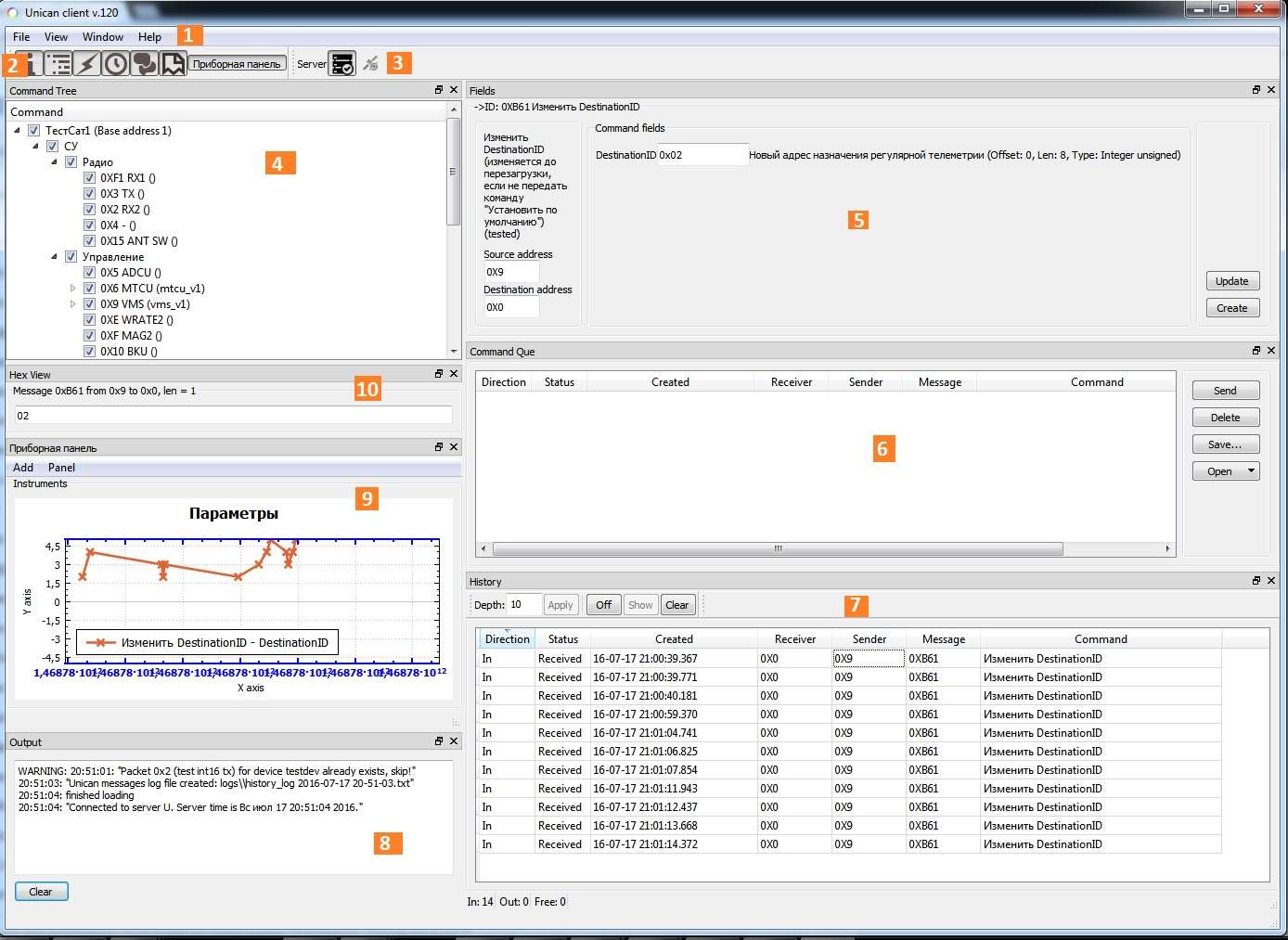
Picture 1. The main window of the Houston Application
The numbers in the figure are indicated by:
- Main menu BY HA;
- The toolbar;
- Connection Status panel;
- Satellite map;
- Command Editor;
- Command queue;
- The history of the exchange on the bus;
- Message output window;
- Custom dashboard;
- A window for viewing the "raw" 16 data of the Unican package.
The main menu provides basic options for managing the view of the main window BY HA, as well as access to help. The main menu items are described below.
File Main menu item
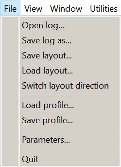
Picture 2. File main menu item
When you select the File main menu item, you have access to the following functions:
- Open log... – select the log file to view;
- Save layout – save the view parameters of the main window;
- Load layout – loading the view parameters of the main window;
- Switch layout direction – switching the alignment of the menu position to the right or left edge of the main window BY HA;
- Load profile – load the selected device configuration;
- Save profile – save the selected device configuration;
- Switch layout direction – switching the alignment of the menu position to the right or left edge of the main window BY HA;
- Parameters – view and edit parameter values BY HA;
- Quit – exit the HA software.
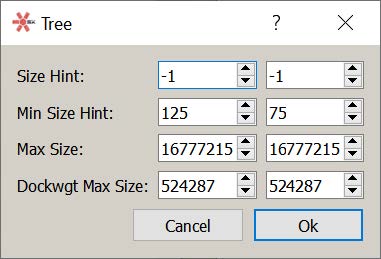
When you select a log file, save and load the main window view parameters, the standard Windows OC window opens to select the save or download file. The window for viewing and editing the values of the HA parameters is shown in Figure 3. At the end of editing the parameters, click the Ok button. By clicking the Cancel button, the results of changing the parameters will be canceled, and the Parameters window will be closed.
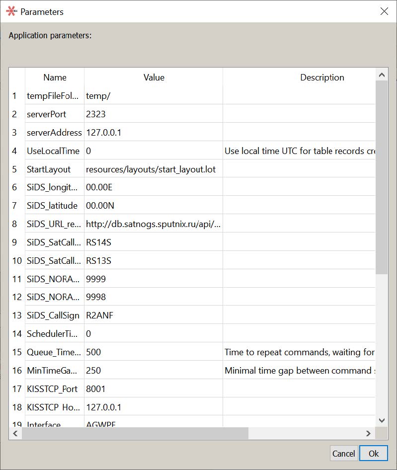
Picture 3. Window for viewing and editing parameter values by Houston Application
View Main Menu item
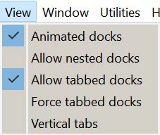
Picture 4. View Main menu item
When you select the main menu item View, you have access to the following functions for managing nested windows:
- Animated docks – not used in the current version;
- Allow nested docks – allow windows to be placed next to each other, not just along the borders of the main window;
- Allow tabbed docks – allow tabs to be made from windows;
- Force tabbed docks – force tabs to be created, preventing new windows from taking up space inside the main window;
- Vertical tabs – display the list of tabs vertically, not horizontally.
Window Main menu item
When you select the main menu item Window, you can access the windows for editing panel properties BY HA, properties of previously created dashboards, and panel creation and deletion functions. The left drop-down window displays a list of panels opened in the main window BY HA, the right drop-down window displays a set of properties of the panel selected in the left window (Picture 5). Panel properties are set or disabled when they are selected with the mouse.
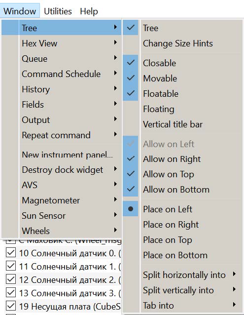
Picture 5. List of panels
The following is available in the panel properties window (Picture 6):
- panel name (in the Tree example);
- Raise (increase) – bring the panel to the foreground;
- Change Size Hints – setting limits on the allowed panel sizes
Picture 6. Panel Properties
- Closable – the panel can be closed;
- Movable – the panel can be moved;
- Floatable – resizing the panel;
- Floating – "detaching" from the main window;
- Vertical title bar – vertical position of the panel name and control buttons;
- Allow on Left – left shift is allowed;
- Allow on Right – right shift is allowed;
- Allow on Top – upshift is allowed;
- Allow on Bottom – downward displacement is allowed;
- Place on Left – place on the left side of the main window;
- Place on Right – place on the right side of the main window;
- Place on Top – place on the top side of the main window;
- Place on Bottom – place on the bottom of the main window;
- Split horizontally into – place the panels in a row horizontally, in the list that opens, specify which panel to install the current panel after;
- Split vertically into – place the panels in a row vertically, in the list that opens, specify below which panel to install the current panel;
- Tab into – to include the panel in the set of bookmarks, in the list that opens, specify which panel to bookmark the current panel to the right of the bookmark.
- Modified – changeable panel.
When you select New instrument panel, the steps to create a new dashboard begin. The Destroy dock widget item is used to delete panels that are active at the time of selecting this item.
Utilities Main Menu item

Picture 7. Utilities Main menu item
When selecting the main menu item Utilities (Picture 7), access to the following functions is provided:
- Unican firmware manager – management of the embedded software of the Unican bus.
When you select the Unican firmware manager function, the firmware configuration window opens (see Picture 8).
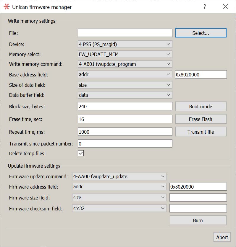
Picture 8. Embedded Software Configuration window
On the Write memory settings panel, the parameters for recording the firmware that is being performed for the first time are entered. The Select button displays a window for selecting the firmware settings file. If there is a file, the firmware parameters are read from the file with the entered values displayed in the input lines of the Unican firmware manager window. If there is no parameter file, their values must be set in the appropriate input lines.
In the input line Device, install the device connected to the Unican satellite bus. The list of devices opens by clicking the icon (see Picture 9). In the input line Memory select, one of the possible memory types FW_UPDATE_MEM, FW_MAIN or FLASH_BASE is set.
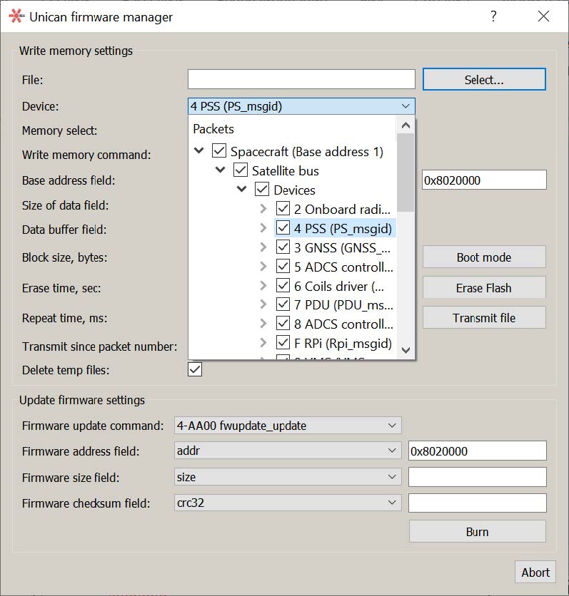
Picture 9. List of devices
In the input line Write memory command, the Write to memory command is set (see Picture 10). In the input lines Base address field, Size of data field and Data buffer field, the values addr, size and data are set from the opening lists. In the additional line for Base address field, the address value in the 16-bit system is entered from the keyboard. In the input line Block size, bytes, use the keyboard to enter the size of the data block when writing in bytes. In the input line Repeat time, ms should enter the repetition time when writing to memory in milliseconds. Setting the Delete temp files flag sets the mode for deleting temporary files after recording is finished.
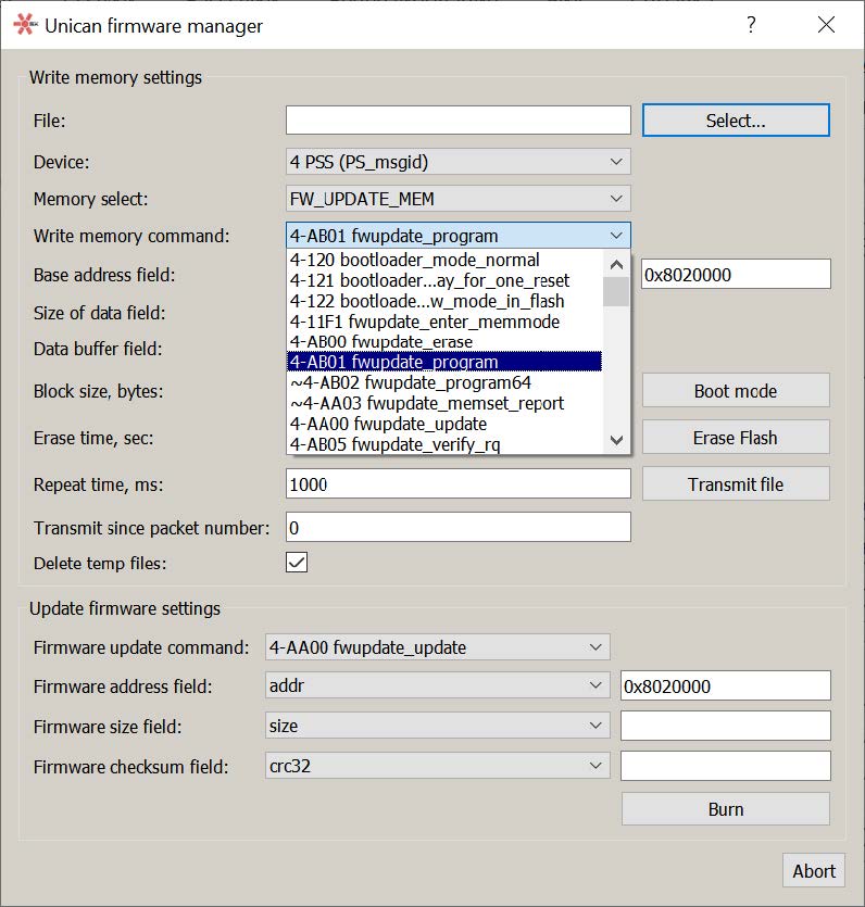
Picture 10. Write to memory command
The Boot mode button sets the boot mode.
The Erase Flash button erases the flash memory of the device.
The Transmit file button transfers the file for recording.
On the Update firmware settings panel, the parameters for updating the firmware settings are entered.
The input lines Firmware update command, Firmware address field, Firmware size field are similar to the corresponding lines of the panel Write memory settings. In the additional line for Firmware size field, the size of the memory area is entered from the keyboard. The line Firmware checksum field sets the checksum type. The additional line shows the value of the checksum of the recorded information, determined during the preparation of the recording.
The firmware is recorded using the Burn button.
The Abort button is used to interrupt the process of transferring the firmware file.
Main menu item Help
When you select the main menu item Help, you have access to the following functions:
- Hot keys... – display of the list of shortcut keys window (Picture 11):
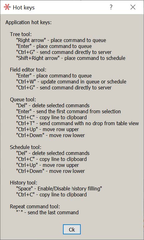
Picture 11. The Hot keys window
- About Qt... – displays the Qt version information window (Picture 12):
Picture 12. About Qt Window
- About... – displays the window of information about the software version number HA (Picture 13):

Picture 13. About Window
Configuration
The following xml files are located in the resources folder:
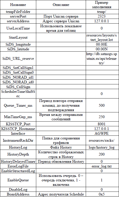
- unican_config.xml – setting general parameters BY HA;
- devices* (devices-not-used*).xml – description of device operation protocols;
- maps*.xml – description of the addressing map of devices connected to the satellite bus, only the file is used from this foldermap.xml .
The formation of xml files is determined by the corresponding xsd schemas.
When the program starts, a message log file is created in the logs\ folder (Picture 14): Working with log files in HS software is performed similarly.
Picture 14. Log file
Connection Status panel
![]()
Picture 15. Connection Status Panel
The connection status panel displays the current status of the client and server connection, and the server connection to the satellite cable network. When running the software, HA attempts to connect to the server (by IP address and port). The user can connect/disconnect manually by clicking on Connect/Disconnect.
Possible server connection statuses displayed in a pop-up window when hovering over the icon:
- No connection – no connection;
- Pending – connection attempt;
- Connected – connection is established;
- Error – connection setup error.
The statuses correspond to the icon states. When the connection is established, an icon becomes active that displays the connection of the server to the satellite's CAN bus connection equipment. When hovering over the cursor, the following statuses are displayed in the pop-up window:
- Connected – connection is established;
- Pending – connection attempt;
- Error – connection error.
The HA software cannot control the connection of the server to the satellite. To change the IP address of the server or port, you need to restart the program.
Log File panel
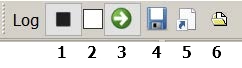
Picture 16. Log File Panel
There are buttons on the log file panel: 1) Start/Stop log registration, which is used to enable/disable log file recording 2) enable/disable structured logs recording 3) convert regular logs to structured ones 4) save the current log to a new file 5) copy the path of the current log file to the clipboard 6) the icon Select new file for regular docs, which opens the standard save window to select a folder and the name of a new log file
Toolbar icon functions
Pictogram Tree – Satellite map
By clicking the icon ![]() the Tree panel of the satellite map is displayed (see Picture 17). The input line is used to set the filtering conditions for the selection of displayed devices (filtering is performed by the names of commands written in Latin letters). The [X] button deletes the filtering conditions. The Filter unknown flag is used to prevent commands for which there is no description from being recorded in the history.
the Tree panel of the satellite map is displayed (see Picture 17). The input line is used to set the filtering conditions for the selection of displayed devices (filtering is performed by the names of commands written in Latin letters). The [X] button deletes the filtering conditions. The Filter unknown flag is used to prevent commands for which there is no description from being recorded in the history.
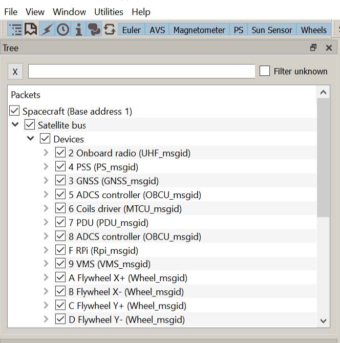
Picture 17. The Tree Panel
The Tree panel provides the user with a complete description of the satellite's cable network and possible data packets transmitted to devices connected to the network and known Houston CC software. Satellite devices are logically grouped by modules and systems. The satellite map determines the addresses of the devices, the address of the ground station with the right to transfer control to the satellite, as well as the codes of data packets (commands and telemetry) sent by the satellite for HA processing.
The tree is built based on the description files (xml files) listed in the configuration file (_resources\maps\map.xml). The file specified in the "SputnikMap" parameter is taken as the top level of the hierarchy. It is used to build a network and device map. The commands for the devices are taken from the description files listed in the configuration file in the parameters named "DeviceDesk". There can be several "DeviceDesk" parameters (description files), unlike the "SputnikMap" parameter, which should be the only one. The devices in the satellite map file map.xml are linked to the description files by the DevModel field of the map.xml file, and there may be several devices of the same model in the map, but at different addresses.
The use of filtering allows you to determine the composition of the messages received. With a large amount of information on the bus, limiting the composition of received messages allows you to avoid losses when receiving messages and improve the visibility of data display. The acceptance permission sign is set next to each entry in the tree, changing the sign on any node changes this sign on all subordinate nodes. The filter can act on satellite systems, modules or devices, as well as on individual types of messages. By default, all messages on the bus are allowed to be received when the application is launched. Hotkeys include "Right arrow" - sending a command to the queue and "Ctrl+G" - sending a command directly to the server.
Fields icon – Command editor
By clicking the icon [i], the command editor panel Fields is displayed, on which commands for satellite systems are generated in the Unican package format in accordance with the description of the device protocol and the satellite map (Picture 18). The protocol description is read at the device address from the satellite map, after which descriptions of the header and command fields are loaded using the message code.
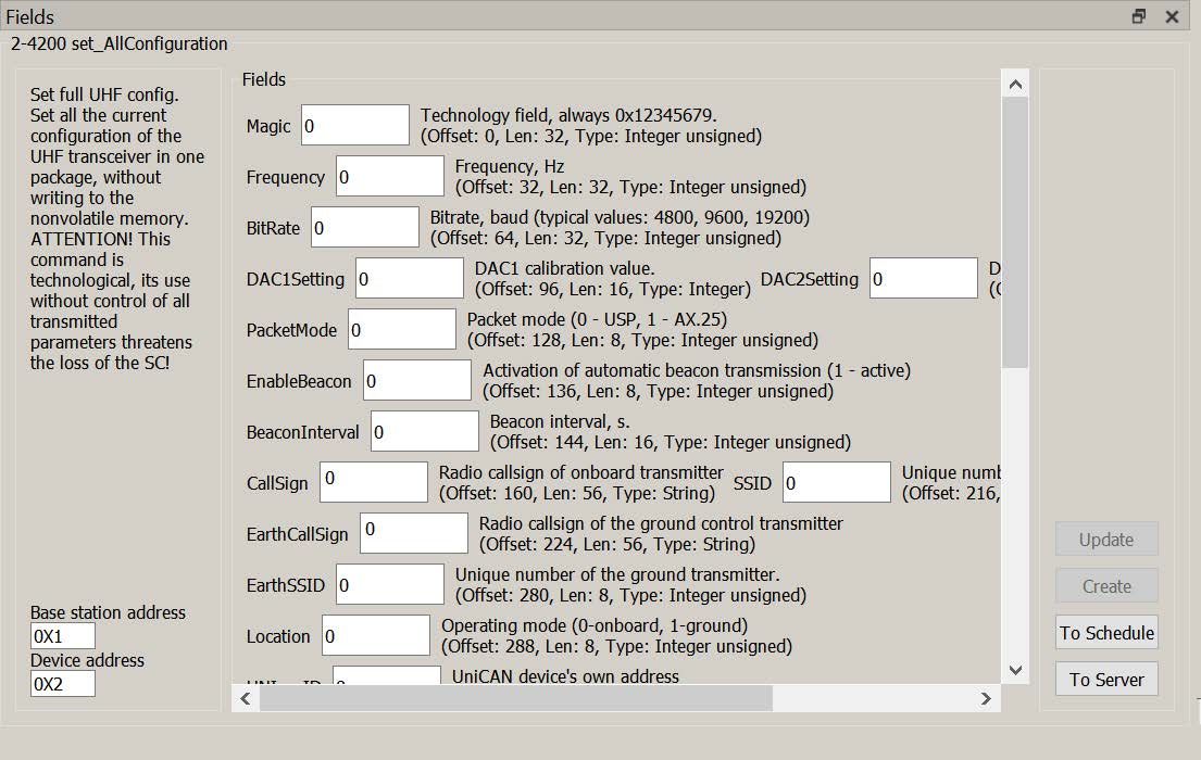
Picture 18. Fields Command Editor Panel
On the Fields tab, the header is displayed on the left as part of:
- the two-byte command code (in the example 1F-4200) and the name (in the example "set_AllConfiguration");
- message description (in the example "Set full UHF configuration...");
- Sender's address (Base station address);
- the recipient's address (Device address).
The sender and recipient addresses are downloaded from the satellite network map file and are available for editing before sending. The command parameter fields, if any, are displayed in the center.
The input element of the field value depends on the data type specified in the device protocol description file. The values of these types Integer unsigned and Float are entered from the input lines, flags are set for data of type Bit.
The message can be sent to the editor from various sources: device tree, exchange history History, command repetition Repeat Command and command queue Queue. To "open" a message in the editor, simply select the desired command with the mouse in any of the listed sources, while for messages from the device tree, the field values are taken "by default" (from protocol files), in other cases, the values previously contained in the message remain.
When a message is "opened" in the editor, a copy of it is created (a new message in the case of the device tree), which gets into the queue by clicking the "Create" button.
The Create button is only available for messages that have the type "command" specified in the protocol description file.
The Update button is used to update the fields in the Queue and Schedule table, available only for messages from the queue, because only they can be changed before sending to the satellite.
The To Schedule button is used to include the generated command in the cyclogram sent to the satellite.
The To server button is used to send the generated command to the server, bypassing the queue of Queue commands.
Messages from the history and messages of the type "datain" (telemetry) can be entered in the Fields panel, but cannot be changed.
Output icon – message output panel
According to the icon Output ![]() the panel for displaying event messages in the HA software opens (Picture 19):
the panel for displaying event messages in the HA software opens (Picture 19):
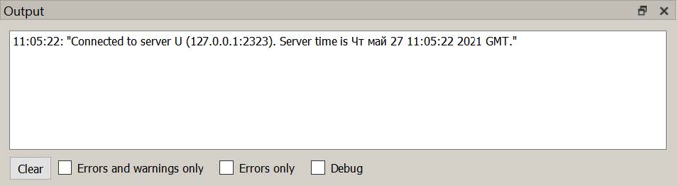
Picture 19. The panel for displaying event messages in the Houston Application software
The Clear button is used to delete all messages from the Output tab.
There are three types of messages in HA software:
- _information – does not require any action from the user, usually contains confirmation of successfully completed actions;
- prediction (marked WARNING) – inform the user about changes in the behavior of the system that need to be taken into account;
- errors (marked ERROR) – non-critical errors, usually related to the integrity of the downloaded data or access to the disk or server. These errors can significantly slow down the work on HA.
The number of messages displayed in the Output window is limited. Except for the Output panel, all HA messages are logged in the error_log.txt file, which is created automatically. This file can be used to debug the program, you should send the error_log.txt file to the developer if incorrect behavior is detected by HA.
Queue icon – command queue
The queue of teams![]() allows you to create a logically complete sequence of commands for satellite systems before sending them over the satellite communication channel (Picture 20):
allows you to create a logically complete sequence of commands for satellite systems before sending them over the satellite communication channel (Picture 20):
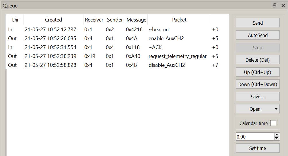
Picture 20. Command Queue
The command queue allows you to visually check the correctness of the time schedule of the entire sequence of commands, edit commands and control the receipt of each command by the target device of the satellite's on-board network. When checking the time schedule, the correctness of the sequence of dates and intervals is determined (the dates must be correct in time and set no earlier than the total intervals). The ability to save the generated command queue to a file and download the previously generated command queue from a file is supported.
The Queue panel contains a queue view table and action buttons. The following columns are displayed in the table:
- Dir – transmission direction, In – messages received on the server from the satellite CAN bus, Out - sent by the server to the CAN bus from this or another client application;
- Created – date and time of creation/receipt of the message by the server (the time of the clock on the server is set);
- Receiver – the Destination field of the Unican message;
- Sender – the Source field of the Unican message;
- Message – Unican message code;
- Packet (for recognized messages) – the name of the command from the protocol file;
- Time to send – the time of sending.
One or more queue commands are selected with the mouse. The keyboard shortcut Ctrl+A is used to highlight all commands. The Fields window is used to view and edit commands.
When you select a command from the queue, its detailed description with the data of the command fields opens in the editor panel, the Update and Create buttons become active. Not only the command data fields are available for editing (if any), but also the addresses of the sender and recipient. This allows you to create commands for devices at addresses not described in the satellite map (for example, when initializing new devices in a cable network).
The Send button and the Enter key are used to send the selected command to the server. If several commands are selected, all selected commands will be sent using the Send button. Only one command is sent using the Enter key, you should press the Enter key sequentially for each highlighted command.
Using the AutoSend button, all commands in the Queue table are sent.
By pressing the Delete (Del) button or the "Del" key on the numeric keypad, the selected command is deleted from the queue.
The Up (Ctrl + "up arrow") and Down (Ctrl + "down arrow") buttons move the selected command one up or down.
The Page Up and Page Down buttons move the selected command to the beginning or to the end of the queue.
Using the Save button, the generated command queue is saved to a file of type .que. To select a file name, the standard Windows save window opens.
The Open button is used to enter a previously saved queue from a file.
When you click the Open button, a list of queues previously saved in the "resources\queues_" folder opens in the drop-down menu. To quickly open a queue file from the default folder, simply click on the menu item with the name of this file. If the queue is saved in another folder, you can use the _From file... option and select the folder and file in the standard dialog box. If any queue was created before opening the file using the Open button in the Queue panel, the commands from the file will be added to the end of the existing queue.
There are two ways to determine when to send queue commands to the server:
- setting the date and time of sending the command when the flag is set Calendar time (Picture 21):
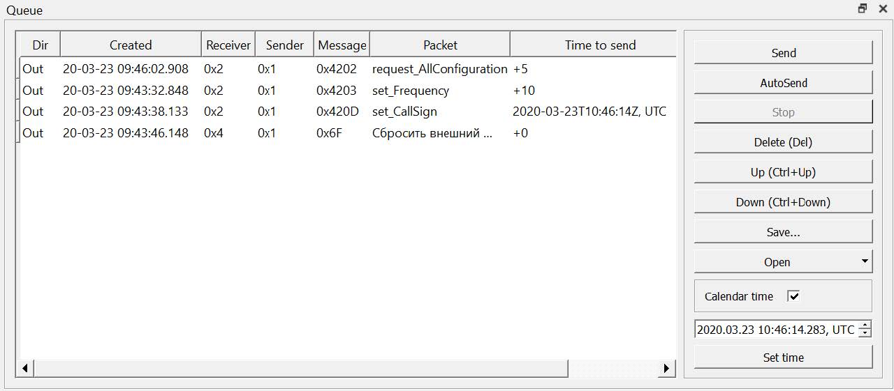
Picture 21. Setting the date and time when the command was sent
- setting the time interval from sending the command by pressing the Autosend button to sending the command when the Calendar time flag is unchecked (Picture 22):
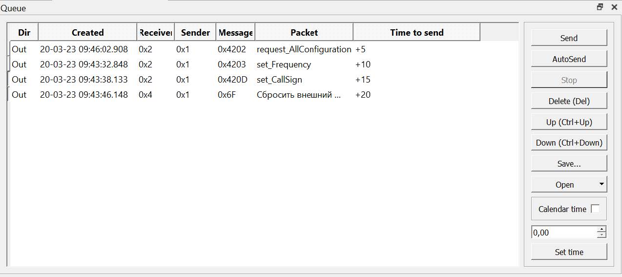
Picture 22. Setting the time interval
When the Calendar time flag is set, the date and time are initially set for queue commands according to the date and time of the user's machine station in UTC format (Picture 23):

Picture 23. Date and time in UTC format with the Calendar time checkbox selected
The set date and time are displayed in the input line located in the column of the control buttons. When you double-click in the field of the Time to send column of the selected command, a similar date and time entry line is displayed in this column. To change the date and time values, select the parameter to be changed with the mouse and set its value using the zoom in/out buttons. The date can be set with a change only in the direction of increase. If the time is changed downwards without increasing the date, the set values will be ignored with an error message (Picture 24):
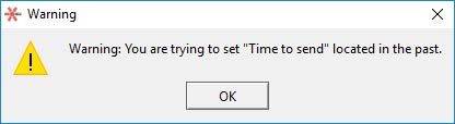
Picture 24. Error message
When you finish setting the date and time parameters, press the Set time button in the input row of the control buttons column. The set value will be displayed in the fields of the Time to send column of the selected command.
When the Calendar time flag is unchecked, the value of the time interval is entered from giving the command to send by pressing the Autosend button until the command is sent. The interval value can be set either in the input line of the button column, or in the input line displayed by double-clicking in the column field Time to send of the selected command. The value of the time interval is set in seconds with an accuracy of two decimal places (tens of milliseconds).
When the time interval is set, press the Set time button in the input row of the control buttons column. The set value will be displayed in the fields of the Time to send column of the selected command. The Queue panel displays both commands and received messages - responses to the transmission of commands. The indication of the response display is the ~ symbol in the Packet field. The response parameters are not editable.
Queue panel hotkeys:
- Delete – delete a command from the queue;
- Enter – sending a dedicated command to the satellite;
- Ctrl+A – highlight all queue commands;
- Ctrl+C – copy selected commands to the clipboard;
- Ctrl+T – sending the selected command without deleting it from the queue.
Attention! It is important to ensure that the queues being opened are compatible with the satellite card used, otherwise sending them may cause unpredictable behavior of the device. To do this, check the queue after opening the file.
History icon - history
By the icon on the History panel ![]() the messages transmitted over the satellite communication channel are displayed in chronological order, including commands sent from the queue (Picture 25):
the messages transmitted over the satellite communication channel are displayed in chronological order, including commands sent from the queue (Picture 25):
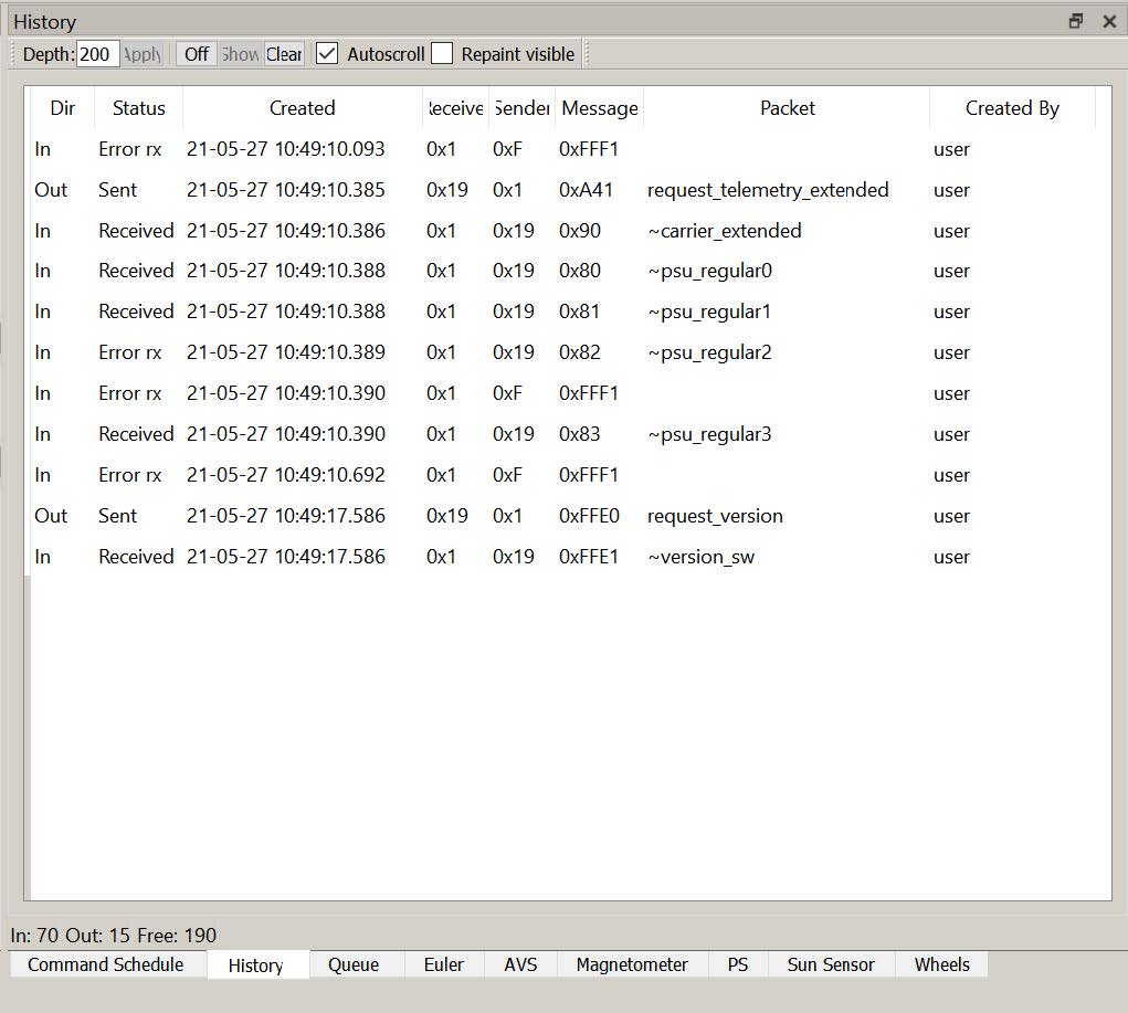
Picture 25. The History window
The history panel consists of a settings area, a tabular part, and a status bar. The following functions are provided in the settings area:
- Depth – the maximum allowed number of records in the history table.
- Apply – change the maximum table size according to Depth;
- Off/On – turn off/turn on the history;
- Show – not used in the current version;
- Clear – clear the table;
- Autoscroll – show current entries in the History window;
- Repaint visible – mode for redrawing only visible rows in the table.
The following fields are displayed in the table part:
- Dir – transmission direction, In – messages received on the server from the satellite CAN bus, Out - messages sent by the server to the CAN bus from this or another client application;
- Status – message status: Received – successfully received from the CAN bus, Sent – successfully sent by the server to the satellite CAN bus, Error tx!
- error sending from the server to the satellite bus, Error rx – error in the message structure (the message does not match the description in xml file).;
- Created – date and time of receipt/sending of the message by the server (the time of the clock on the server is set);
- Receiver – Destination field of the Unican message;
- Sender – the Source field of the Unican message;
- Message – Unican message code;
- Packet (for recognized messages) – the name of the command from the protocol file;
- Created by – login of the user who created the message.
The status bar shows statistics from the moment the application was launched:
- In – number of incoming messages;
- Out – number of outgoing messages;
- Free – the number of free entries in the history panel, when this number is reached, old messages will be deleted.
All messages, both incoming and outgoing, get into the history panel. If a message sent to the server by any HA client is broadcast to all HA clients connected to this server, then this message is displayed to all HA clients.
If the incoming command is successfully recognized (the addressee is found in the satellite map and the message code is in the corresponding protocol file), then the HA software substitutes the name of the command from the description file in the Packet field. All functions of the HA software are available for recognized commands (viewing fields, adding to dashboards, etc.).
Filters installed on the Tree panel can be used to filter incoming messages. Filters only work for recognized commands.
Attention! With intensive exchange on the bus (more than 25 messages per second), an active history panel with a large Depth value (more than 30) can significantly affect HA performance. This is due to the peculiarities of redrawing the screen and may lead to the inability of the program to respond to user actions.
To avoid such situations during intensive exchange, the following actions can be taken:
- specify a small value Depth;
- Set an incoming message filter;
- hide the History panel (by clicking on the toolbar or behind another panel as a tab);
- disable history management with the Off button.
When history is disabled, all information about the exchange over the satellite communication channel is saved in the message log file and can be displayed both in the Houston CC software and by means of other software (for example, Microsoft Excel).
Hex View Icon
According to the icon Hex View ![]() a panel for viewing the hexadecimal code of the Unican package is displayed. The header and contents of any package in the history or queue can be displayed (Picture 26):
a panel for viewing the hexadecimal code of the Unican package is displayed. The header and contents of any package in the history or queue can be displayed (Picture 26):
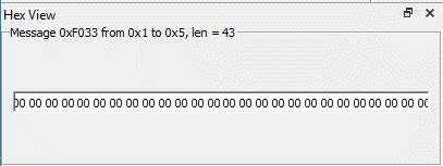
Picture 26. Hex View Window
Unlike the Fields field editor, unrecognized packages can be displayed in the hexadecimal code viewer panel. The packet header fields are shown as a string, where Message is the two-byte message code, from is the sender's address, to is the recipient's address, len is the length of the data (in addition to the message code). The data, if available, is displayed in a single field on the panel in hexadecimal format.
Repeat command icon
According to the icon Repeat command ![]() the command repetition panel is displayed (Picture 27). This panel is a simple means of forming a queue of previously formed commands and sending commands to the server. When you click the Repeat button, a command that is a copy of the selected command, except for the date and time of creation, will be entered at the end of the queue. When the to Queue button is pressed, the command is entered at the end of the queue.
the command repetition panel is displayed (Picture 27). This panel is a simple means of forming a queue of previously formed commands and sending commands to the server. When you click the Repeat button, a command that is a copy of the selected command, except for the date and time of creation, will be entered at the end of the queue. When the to Queue button is pressed, the command is entered at the end of the queue.
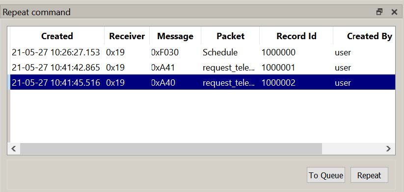
Picture 27. Command Repetition Panel
The following fields are displayed in the command repetition panel:
- Created – date and time when the message was received/sent by the server (the time of the clock on the server is set);
- Receiver – recipient, Destination field of the Unican message;
- Message – Unican message code;
- Packet (for recognized messages) – the name of the command from the protocol file;
- Record Id;
- Created by – login of the user who created the team.
Command Schedule Panel
Panel Command Schedule - command schedule (Picture 28):

Picture 28. Team schedule
The Command Schedule panel contains a schedule view table and action buttons. The following fields are displayed in the table:
- Created – date and time of creation/receipt of the message by the server (the time of the clock on the server is set);
- Receiver – recipient, Destination field of the Unican message;
- Sender – sender, the Source field of the Unican message;
- Message – Unican message code;
- Packet (for recognized messages) – the name of the command from the protocol file;
- Time to send – the time of sending.
You can select one or more schedule commands with the mouse. The keyboard shortcut Ctrl+A is used to highlight all commands. To view and edit commands, use the Command Editor.
When you select a command from the schedule, its detailed description with the data of the command fields opens in the editor panel, the Update and Create buttons become active. Not only the command data fields are available for editing (if any), but also the addresses of the sender and recipient. This allows you to create commands for devices at addresses not described in the satellite map (for example, when initializing new devices in a cable network).
Using the Send Schedule button, the cyclogram is sent in one data packet.
By pressing the Delete (Del) button, the selected command is deleted from the schedule.
The Up (Ctrl + "up arrow") and Down (Ctrl + "down arrow") buttons move the selected command one up or down.
The Page Up and Page Down buttons move to the beginning or end of the schedule.
Using the Save button, the generated command schedule is saved to a file of the .sch type. To select a file name, the standard Windows save window opens.
The Open button is used to enter a previously saved schedule from a file.
When you click the Open button in the standard Windows dialog box, the folder "resources\schedules\" opens (the folder name is configured in the configuration file). If the schedule is saved in another folder, you can use the tools of the dialog box to select a folder and a file. If any schedules were created before opening the file using the Open button in the Command Schedule panel, the commands from the file will be added to the end of the existing schedule.
The date and time parameters are determined in the same way as working with the Queue panel.
Keyboard shortcuts:
- Ctrl+A – highlight all queue commands;
- Ctrl+C – copy the selected commands to the clipboard.
- Up (Ctrl + "up arrow") and Down (Ctrl + "down arrow") - move the selected command one up or down.
- Page Up and Page Down - move to the beginning or end of the list.