Assembly of the PSS module (power supply system)
The power supply system contains a power supply board and rechargeable batteries that provide power to all OrbiCraft 3D modules. The batteries are charged from the 220V mains using the power supply included in the kit.
Components required for assembly (Picture 1):
- all parts labeled PSS (two bases, two walls, two transparent panels);
- PSS board;
- Batteries;
- fasteners (brass racks PCHSS – M3x22 – 4 pcs., cylindrical head screws – M3x6 – 4 pcs., countersunk head screws M3x10 – 4 pcs.).
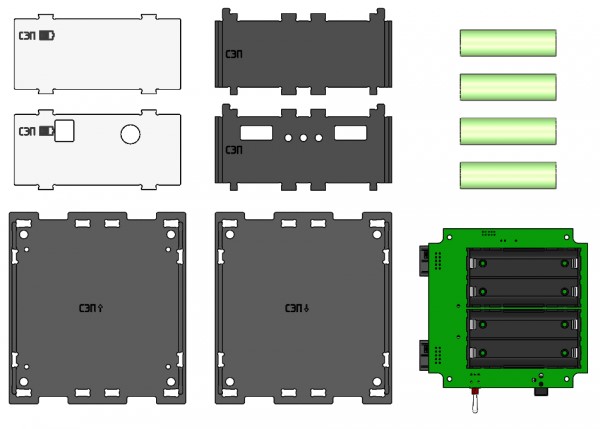
Picture 1. Components for module assembly
Assembly order
1) Take the lower base of the PSS (marked: PSS ↓), install four brass racks PCHSS – M3x22 on top, fix them from below with four screws with a countersunk head M3x10 (Picture 2):
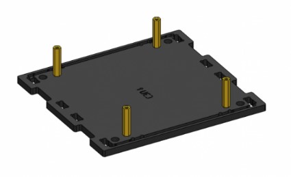
Picture 2. Mounting of brass racks
2) Install the batteries in the special seats of the PSS board. When installing batteries, it is IMPORTANT to observe the polarity. (Picture 3):
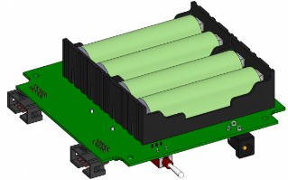
Picture 3. Installing the battery
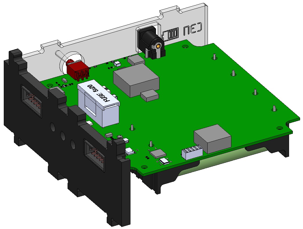
3) Insert the connectors of the PSS board into the cutouts of the transparent panels (Picture 4):
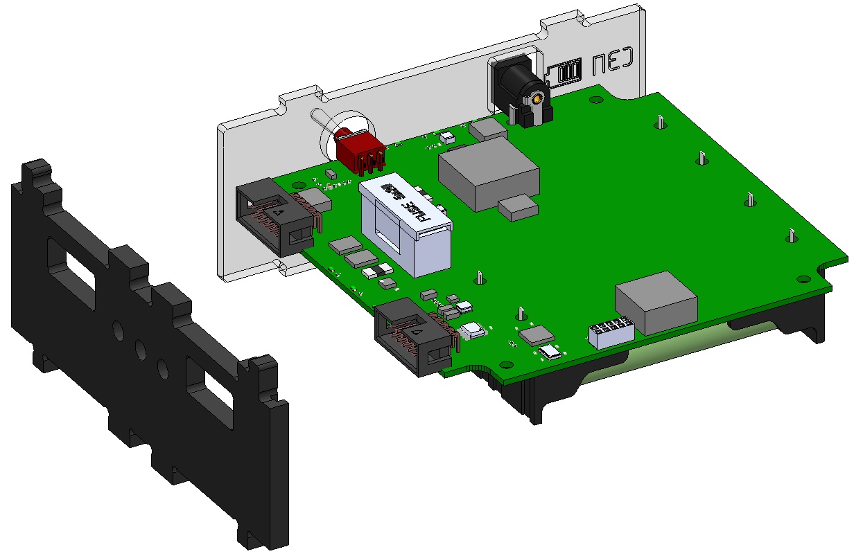
Picture 4. Installing a transparent panel
4) Insert the connectors of the PSS board into the cutouts of the side wall, while aligning the side surface of the window with the recess in the side wall (Picture 5):
Picture 5. Installing the side wall
5) Install the board with a side wall, transparent panel and batteries on the bottom base. To do this, combine the projections of the side wall and the window with the holes in the base and snap it. Fix the board with M3x6 screws with a cylindrical head (Picture 6):
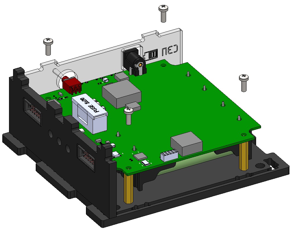
Picture 6. Mounting the board
6) Fix the second side wall on the base. To do this, align the projections of the side wall with the holes in the base and snap (Picture 7):
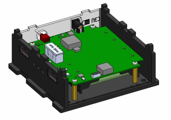
Picture 7. Installation of the second side wall
7) Fix the second transparent panel on the bottom base. To do this, slide the panel along the guides in the walls to the base and snap it (Picture 8):
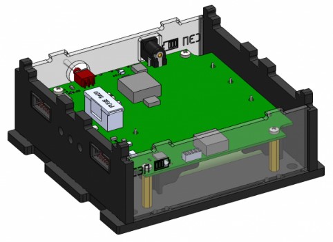
Picture 8. Installing the second panel
8) Attach the top cover (marked: PSS↑) to the assembled housing. To do this, combine the cutouts on the top cover, the protrusions of two walls and two transparent panels, and snap them with effort. This is what the assembled PSS module looks like (Picture 9):

Picture 9. Assembled PSS module