Assembling the ground HF module (high frequency waves)
The HF ground module is a device containing a transceiver that allows receiving data (images or information) using an IR receiver. With the help of the HF ground module, directional data transmission is simulated at a speed of 115,200 bits/s. To transmit data, place the receiver and transmitter opposite each other at a distance of no more than 1 m.
Components required for assembly (Picture 1):
- All parts labeled HF (two side covers, bracket, back cover, front ring, upper and lower base);
- additional parts (rings – 3 pcs.);
- boards (HF board, USB-UART converter);
- cable for connecting the HF board and the adapter board;
- fasteners (brass racks PCHSS M3x12 – 4 pcs., brass racks PCHSN M3x18 – 4 pcs., countersunk head screws M3x10 – 8 pcs., M3x20 – 2 pcs., cylindrical head screws M3x12 – 4 pcs.)
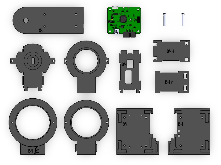
Picture 1. Components for module assembly
Assembly order
1) Arrange the four rings in the order from the smallest to the largest and connect them with two M3x20 screws. (The big ring is marked with: HF + logo) (Picture 2):
![Ring assembly]
Picture 2. Assembling the rings
2) Align the board with the back wall (marked: HF) (Picture 3):
![Installing a board with a back wall]
Picture 3. Installing the board with the back wall
3) Connect the back wall to the lower base (marked: HF↓) and the upper base (marked: HF↑). To do this, combine the projections of the back wall with the holes in the upper and lower base and snap (Picture 4):

Picture 4. Installation of bases
4) Connect the structure with four rings. To do this, combine the protrusions of the small ring with the holes of the lower base and snap it. The small ring and the upper base do not have special elements for connection (Picture 5):
![Connecting the structure to the rings]
Picture 5. Connection of the structure to the rings
5) Attach countersunk head screws M3x10 (4 pcs.) and brass posts with internal thread PCHSS M3x12 (4 pcs.) to the side wall (marked: HF) (Picture 6):
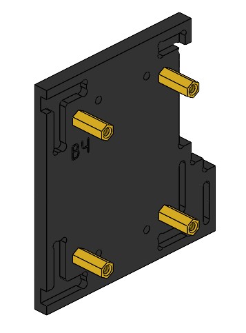
Picture 6. Mounting to the side wall
6) Connect the side wall to the rest of the structure. To do this, position the cutouts in the side walls with protrusions of the upper and lower bases, the back wall, rings and snap them. Next, fix the board using brass racks with internal and external threads PCHSN M3x18 (4 pcs.) (Picture 7):
![Sidewall connection]
Picture 7. Connection to the side wall
7) Connect the second side wall to the rest of the structure. Position the cutouts in the side walls with the projections of the upper and lower bases, back wall, rings and snap. Fix the side wall with M3x10 screws (4 pcs.). Attach the bracket to the assembled housing with M3x12 screws (4 pcs.) (if necessary, attach the module to the profile) (Picture 8):
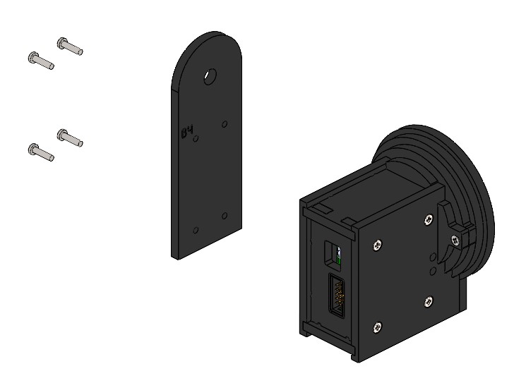
Picture 8. Installing the second side wall and bracket
8) Connect two LEDs to the side cover (Picture 9):

Picture 9. Installation of light-emitting diodes
A fully assembled device looks like this (Picture 10):
![Assembled module]
Picture 10. The assembled module