Assembly of the OBC module (on-board computing module)
The onboard computing module is the main module that provides processing and sending of telemetry generated in the angular velocity sensor (AVS) and magnetometer. It also provides access to the Raspberry Pi board via a Wi-Fi module or CAN connection, as well as to calculate the orientation of the satellite using the orientation and stabilization System (SOS) microcontroller. Also, using the Wi-Fi module installed on the OBC, the connection to the computer takes place.
Telemetry is the remote collection, processing and sending of data using various sensors.
Components required for assembly (Picture 1):
- all parts labeled OBC (two bases, two walls, two transparent panels);
- OBC board;
- fasteners (screws with a cylindrical head M3x6 – 4 pcs.).
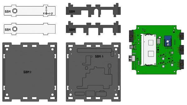
Picture 1. Components for module assembly
Assembly order
1) Install the OBC board on the lower base (marked: OBC ↓) (Picture 2):
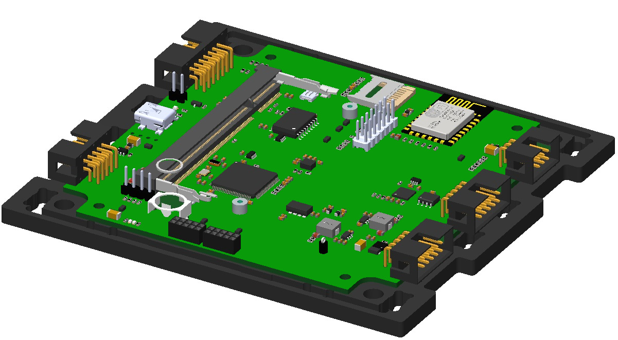
Picture 2. The foundation of the OBC
2) Fix the board on the lower base with M3x6 screws with a cylindrical head (Picture 3):
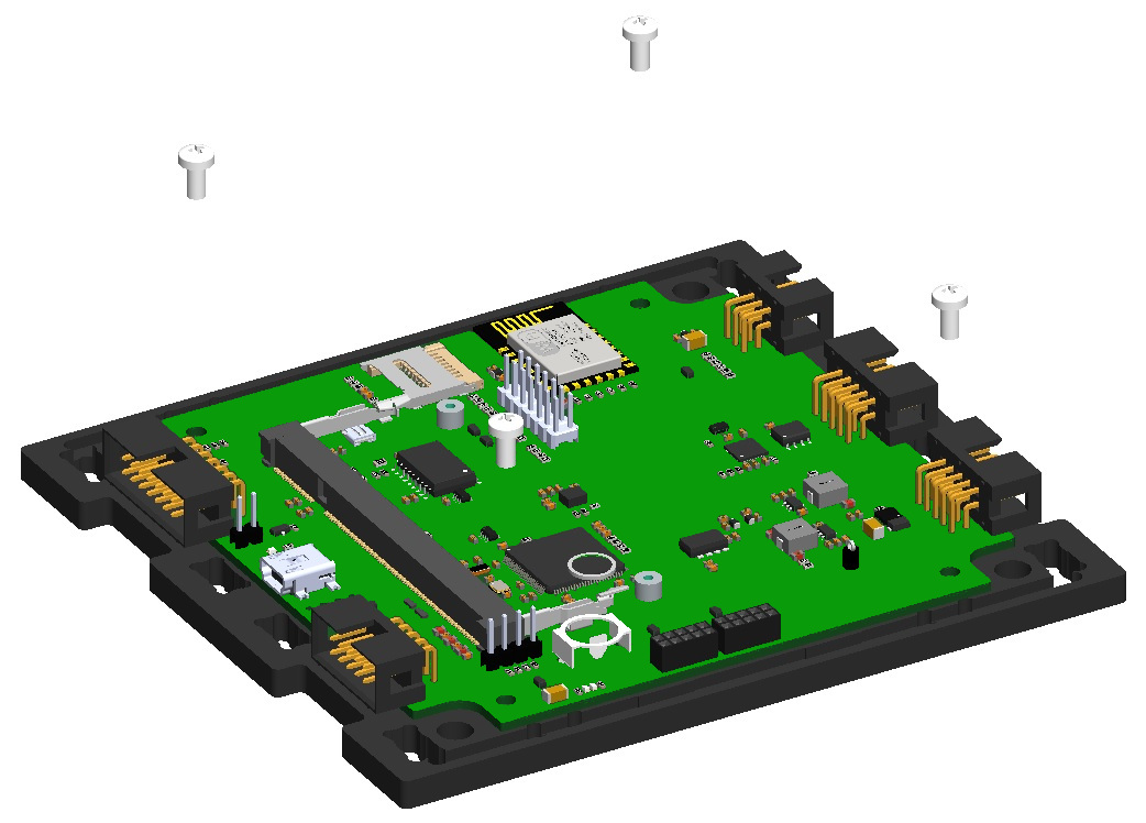
Picture 3. Mounting the board
3) Fix the side walls on the lower base. To do this, combine the projections of the side walls with the holes in the base and snap (Picture 4):
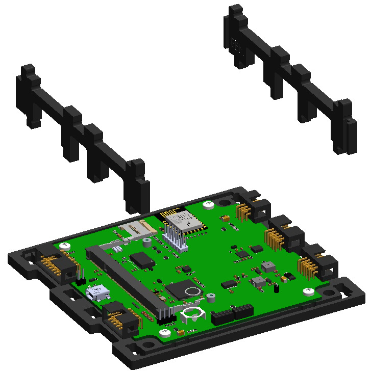
Picture 4. Installation and fastening of side walls
4) Fix two transparent panels on the bottom base. To do this, hold each panel along the guides in the walls to the base and snap it. Observe the location and orientation of the panels with axes as in the figure below (Picture 5):
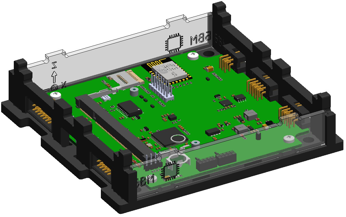
Picture 5. Mounting of two transparent panels
5) Attach the top cover (marked: OBC↑) to the assembled housing. To do this, combine the cutouts on the top cover, the protrusions of two walls and two panels, and snap them with effort (Picture 6):
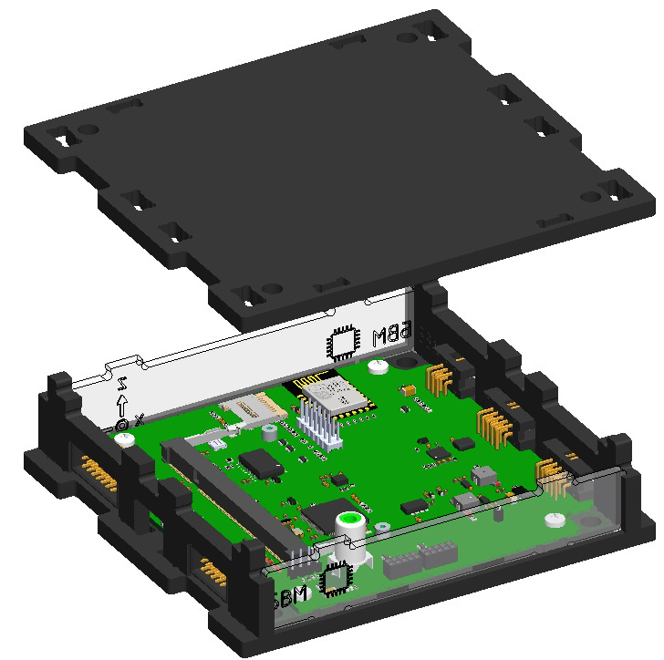
Picture 6. Installing the top cover
This is what the assembled OBC module looks like (Picture 7):
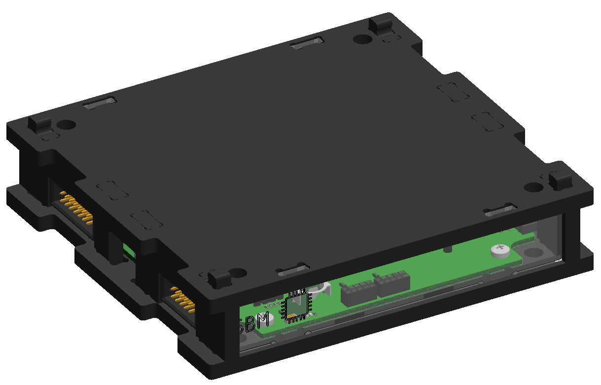
Picture 7. Assembled OBC module