Assembly of the ground UHF module (ultrashort waves)
The UHF ground module is a device that allows the exchange of information between the MCC and the on–board UHF using the Houston Application. The UHF ground module simulates directional data transmission at a speed of 9600 bps. The frequency is 435..437 MHz. The distance between the ground and on-board UHF can be up to 100 m in open space.
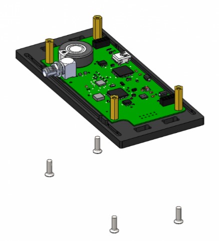
Components required for assembly (Picture 1):
- all parts labeled UHF (two bases, two walls, two transparent panels);
- UHF board;
- antenna;
- fasteners (brass racks PCHSS M3x15 – 4 pcs., countersunk screws M3x10 – 8 pcs.).
![Components for building the module]
Picture 1. Components for module assembly
Assembly order
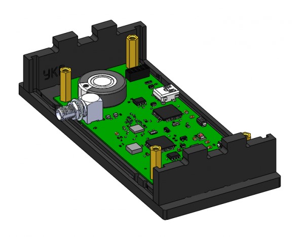
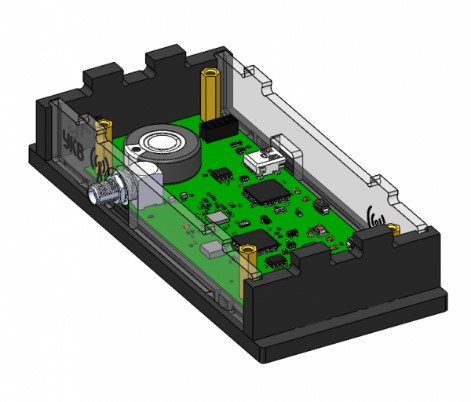
1) Install the UHF board on the lower base (marked: UHF ↓). Secure the board with four brass PCHSS M3x15 posts and four countersunk head screws M3x10 (Picture 2):
Picture 2. Installing the board
2) Install the side walls on the lower base. To do this, align the projections of the side walls with the holes in the base and snap (Picture 3):
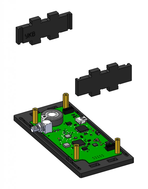
Picture 3. Installing the side walls
3) Install two transparent panels on the bottom base. To do this, hold each panel along the guides in the walls to the base and snap (Picture 4):
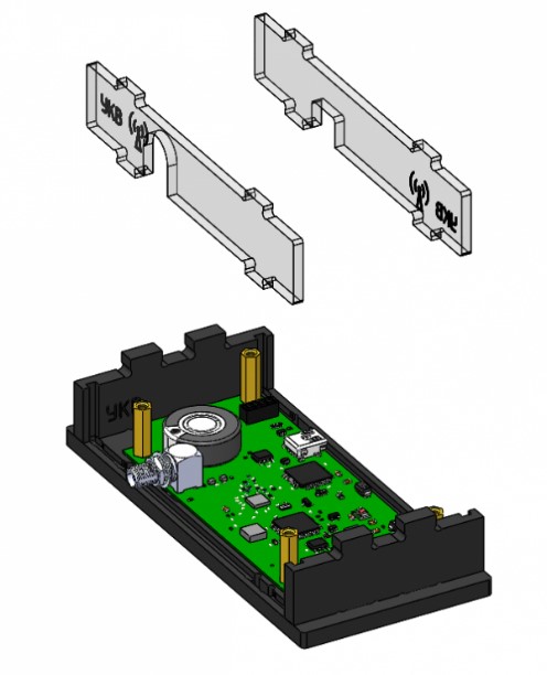
Picture 4. Installing transparent panels
4) Install the top cover (marked: UHF↑) on the assembled housing. To do this, combine the cutouts on the top cover, the protrusions of two walls and two transparent panels, and snap them with effort (Picture 5):
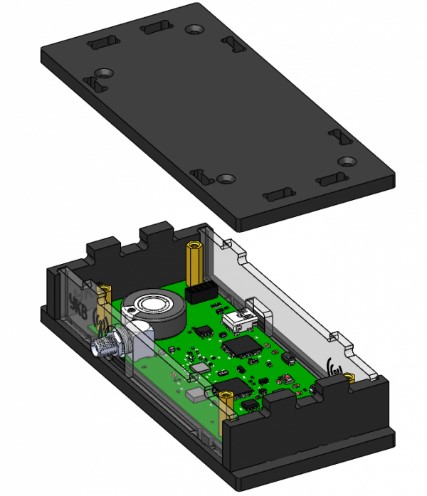
Picture 5. Installing the top cover
5) Fix the lid with four countersunk head screws M3x10 (Picture 6):
![Fixing the lid with screws]
Picture 6. Fixing the lid with screws
6) Connect the antenna to the UHF board. The assembled UHF ground module looks like this (Picture 7):
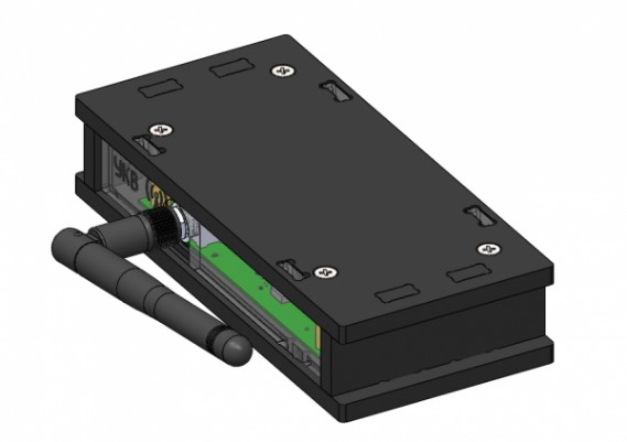
Picture 7. Assembled module with antenna