Assembly of the payload module
The spacecraft contains in its composition the target equipment that ensures the fulfillment of its main mission. This equipment, for which the spacecraft is being created, is called a payload.
The basic structure of the OrbiCraft 3D designer has one payload - a camera as part of the UHF+HF+ERS module. To create your own payloads, you can use the Arduino hardware and software platform included with the payload unit.
The information exchange between the Arduino microcontroller and the on-board computer takes place using an expansion board (the so-called Shield), which is installed on a board with a microcontroller. The expansion board contains a connector for connecting to the cable network via a standard designer cable. Six sensors can be connected to the Troyka Slot Shield board, which are used for various Arduino-based projects.
Components required for assembly (Picture 1):
- all parts labeled payload (two bases, two walls, two transparent panels);
- additional parts (guides – 4 pcs., cover – 1 pc., stop – 1 pc., bracket for arduino MEGA2650 board – 1 pc., bracket for Troyka Slot Shield board – 1 pc.);
- boards (payload board – 1 pc., arduino MEGA2650 board – 1 pc., Troyka Slot Shield board – 1 pc.);
- fasteners (screws with a cylindrical head M2x6 – 9 pcs., M3x12 – 6 pcs., M3x8 – 2 pcs.).
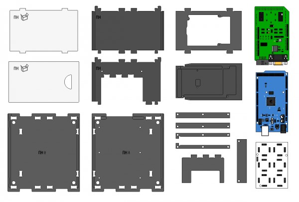
Picture 1. Components for module assembly
Assembly order
1) Install L-shaped guides on the lower base (marked: payload ↓) (Picture 2):
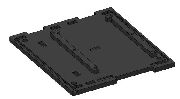
Picture 2. Installation of L-shaped guides
2) Install straight guides on top of them and fix them on the base with six M3x12 screws (Picture 3):
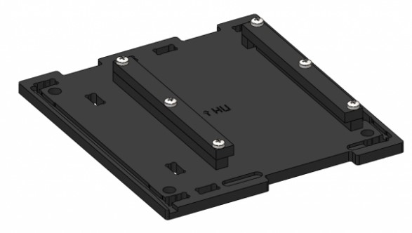
Picture 3. Installing straight guides
3) Attach the Arduino MEGA2650 payload board to the bracket with six M2x6 screws. Install the ArdShield board on top. Mounting with connectors (Picture 4):
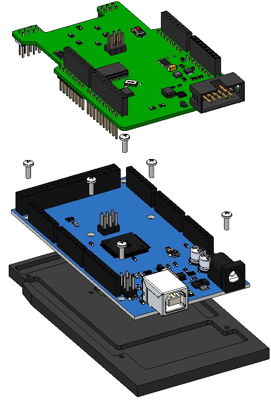
Picture 4. Installing the MON board and the ArdShield board
4) Install the bracket with the boards on the lower base along the guides (Picture 5):
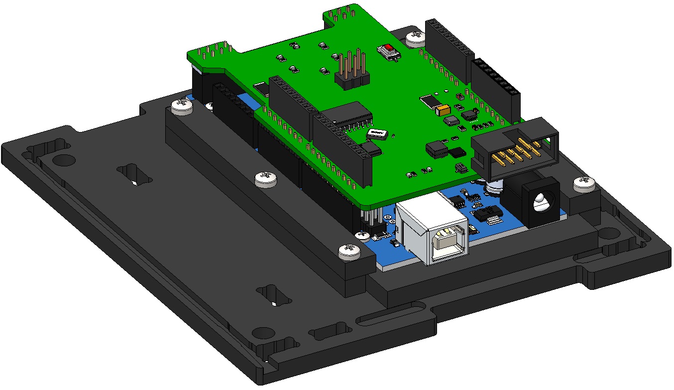
Picture 5. Installing the boards on the base
5) Attach the Troyka Slot Shield board to the bracket with three M2x6 screws (Picture 6):
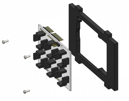
Picture 6. Mounting the Troyka board
6) Install the bracket with the fixed Troyka Slot Shield board on the lower base. To do this, align the protrusions of the bracket with the holes in the base and snap (Picture 7):
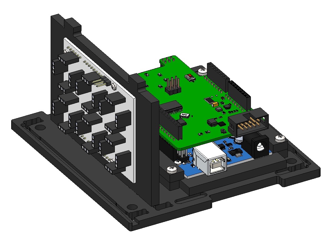
Picture 7. Installing the Troyka board on the base
7) Attach the stop to the side wall using two M3x8 screws (Picture 8):

Picture 8. Fixing the stop to the side wall
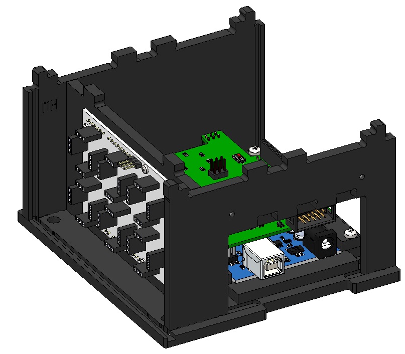
8) Install the side wall with an emphasis on the lower base. To do this, align the projections of the side wall with the holes in the base and snap (Picture 9):
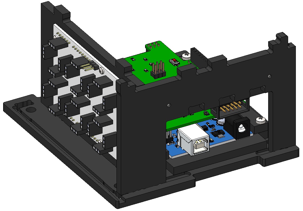
Picture 9. Installation of the side wall with an emphasis on the base
9) Install the second side wall on the base (Picture 10):
Picture 10. Installing the second side wall on the base
10) Install the transparent panel on the bottom base. To do this, slide the panel along the vertical guides in the walls to the base and snap it (Picture 11):
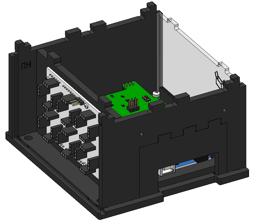
Picture 11. Installing a transparent panel
11) Install the top cover on the assembled housing. To do this, combine the cutouts on the top cover and the protrusions of the two walls, the transparent panel and the bracket, and snap it with effort (Picture 12):
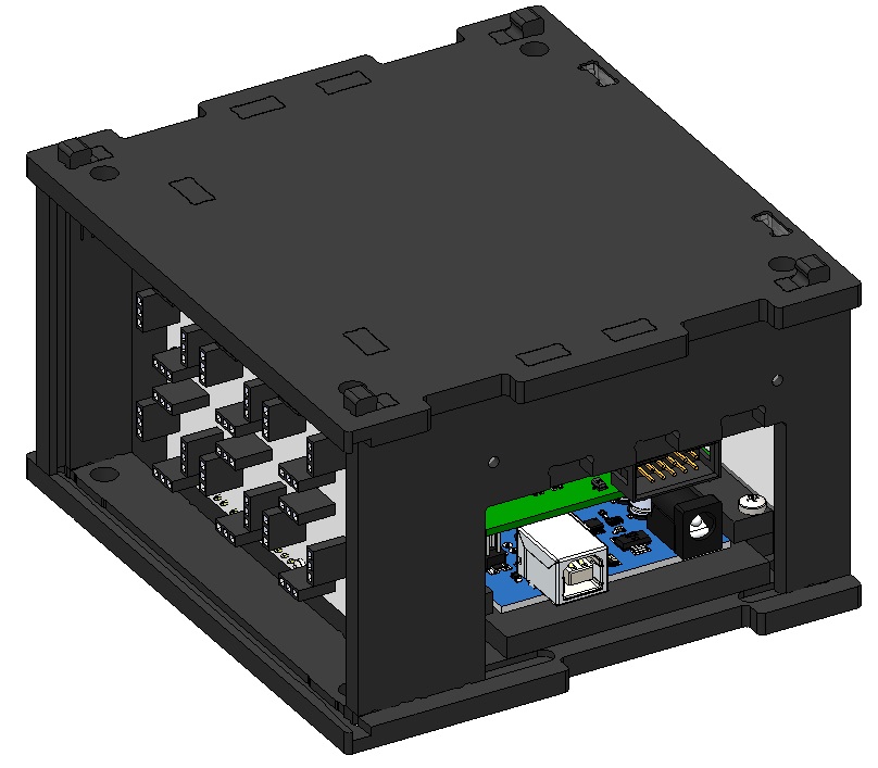
Picture 12. Installing the top cover
12) Install a second transparent panel. To do this, run it along the horizontal guides in the bases. (If additional payload shields are used, do not install) (Picture 13):
Picture 13. Installing a second transparent panel
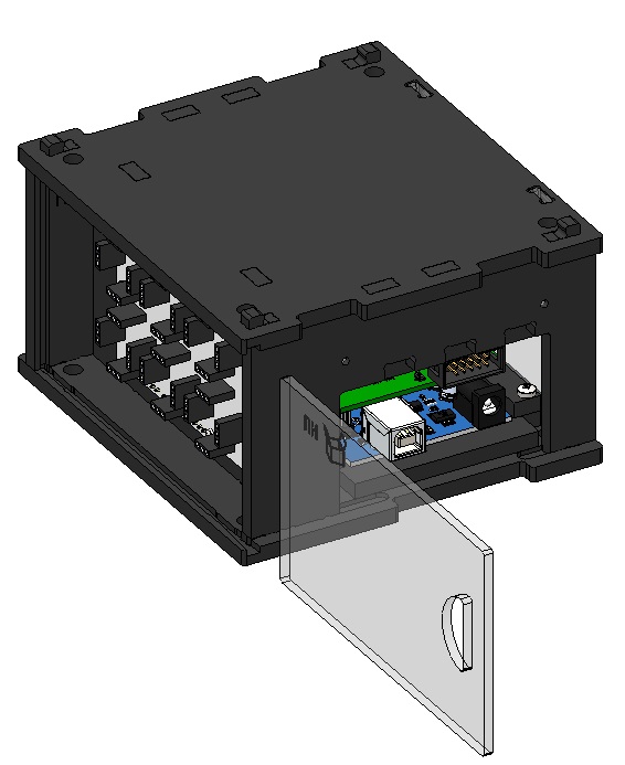
13) Install the cover. To do this, insert it at an angle into the slots in the lower base, and then turn it vertically and insert it into the slots in the side wall (Picture 14):
Picture 14. Installing the side cover
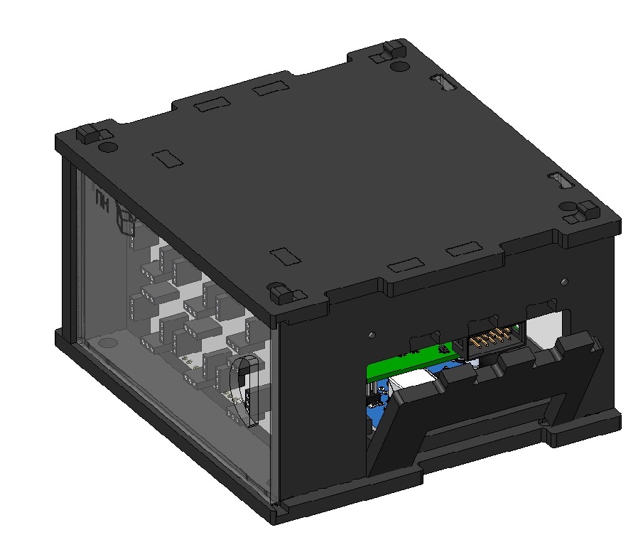
The assembled payload module looks like this (Picture 15):
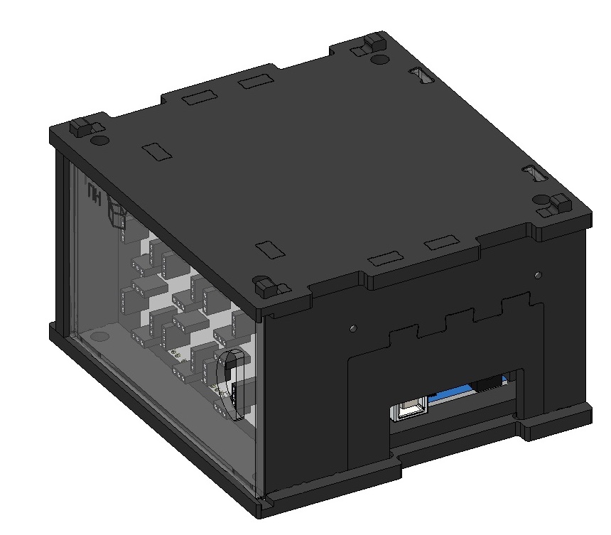
Picture 15. The assembled module