Instructions for assembling OrbiCraft 3D in a uniaxial configuration
Components required for assembly (Picture 1):
- Modules (RW, payload, PSS, OBC, SS, UHF+HF+ERS);
- lower base, instrument legs – 4 pcs., M3x5 cylindrical head screws – 4 pcs. (assembled);
- upper base – 1 pc., nut M4 – 1 pc. (assembled);
- fasteners (M4 stud – 2 pcs., M4 grooved nuts – 2 pcs.);
- cables (6-pin – 1 pc., 14-pin – 1 pc., 10-pin – several pieces).
- terminator.
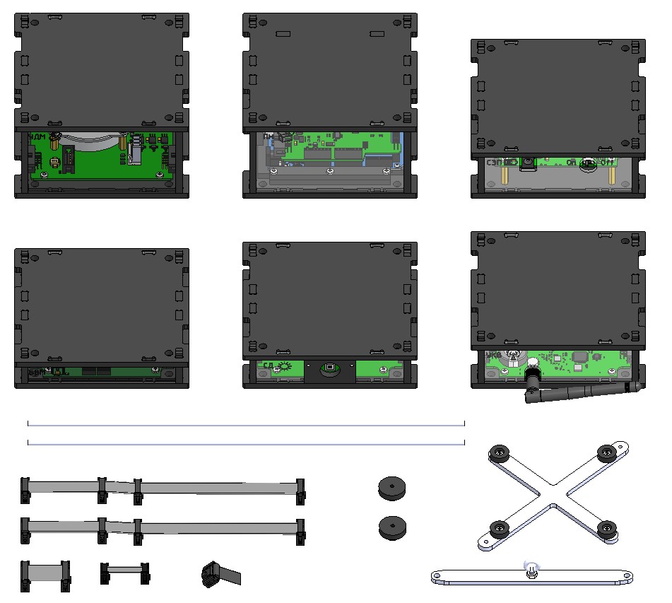
Picture 1. Modules for building the satellite constructor
Assembly order
1) Take the lower base, instrument legs – 4 pcs., screws with a cylindrical head M3x5 – 4 pcs. (already assembled), install the first module on it so that the four threaded holes in the base coincide with the four holes in the module. The figure shows the PSS module (Picture 2):
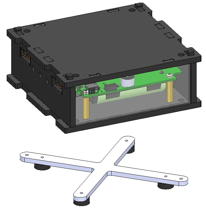
Picture 2. Installation of the base
2) Install the next module from above by aligning the four projections of the lower module with the four cutouts of the upper module (Picture 3):
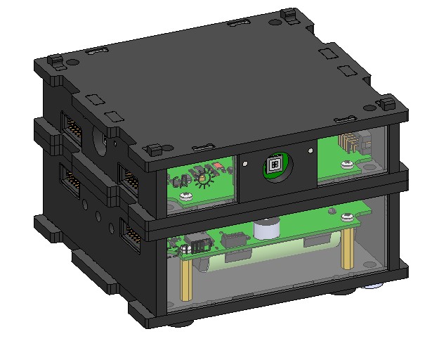
Picture 3. Installing the next module
3) Install all six modules (RW, payload, PSS, OBC, SS, UHF+HF+ERS), each time combining the four projections of the lower module with the four cutouts of the upper module (Picture 4).
For more accurate magnetometer readings, do not install PSS and OBC modules on top of each other, and do not put RW and OBC close together.
Install two M4 studs into the holes of the modules (any two diagonally) and screw them into the threaded holes of the lower base. Take the upper base – 1 pc., the M4 nut – 1 pc. (already assembled) and install them on top of the last module, positioning it with two projections of the M4 stud. Secure the base by tightening two M4 grooved nuts on the M4 studs. Also tighten the two M4 nuts from the bottom.

Picture 4. Assembling a uniaxial OrbiCraft 3D configuration
Connect the modules to each other with cables. Connect the terminator (Picture 5):
Picture 5. Connecting with cables
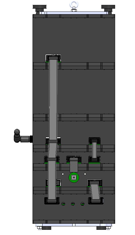
Picture 6. Connecting with cables
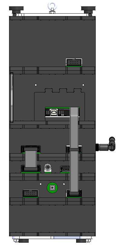
4) The assembled device looks like this (Picture 7):
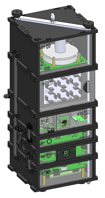
Picture 7. Assembled satellite constructor (uniaxial configuration)