Assembly of the solar sensor module (SS 2D)
Components required for assembly
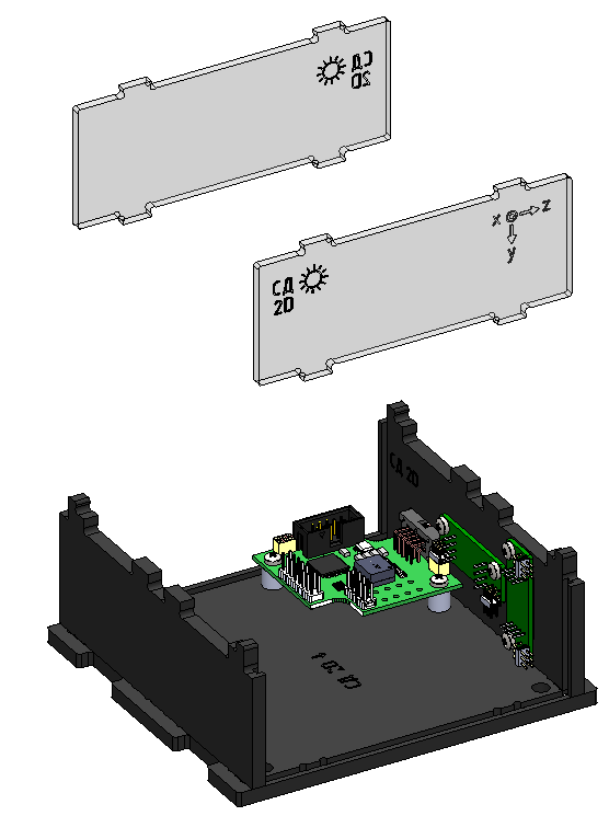
Components required for assembly (Picture 1):
- all parts labeled SS 2D (two bases, two walls, two windows);
- boards (universal board – 1 pc, solar sensor board with mask board – 2 pcs);
- train;
- fasteners (white plastic washers – 2 pcs., cylindrical head screws M3x12 – 2 pcs., M3x6 – 4 pcs.).
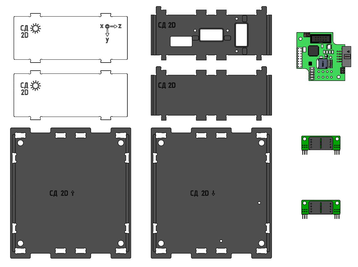
Picture 1. SS module configuration
Assembly order
1) Connect the solar sensor board to the universal board (Picture 2):
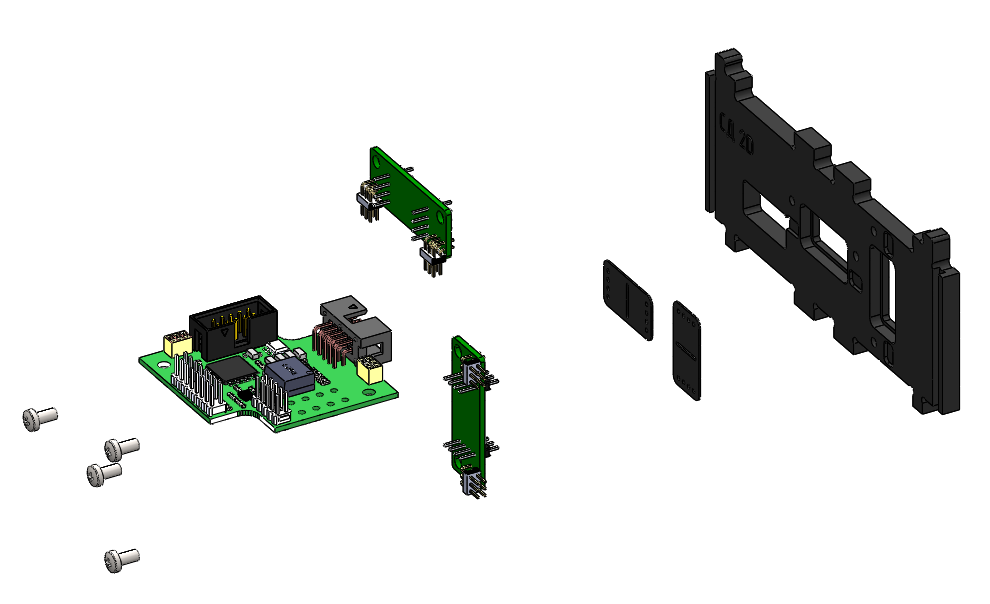
Picture 2. Mounting the SS board
2) Connect the solar sensor mask to the solar sensor board (Picture 3):
Picture 3. Mounting the solar sensor mask
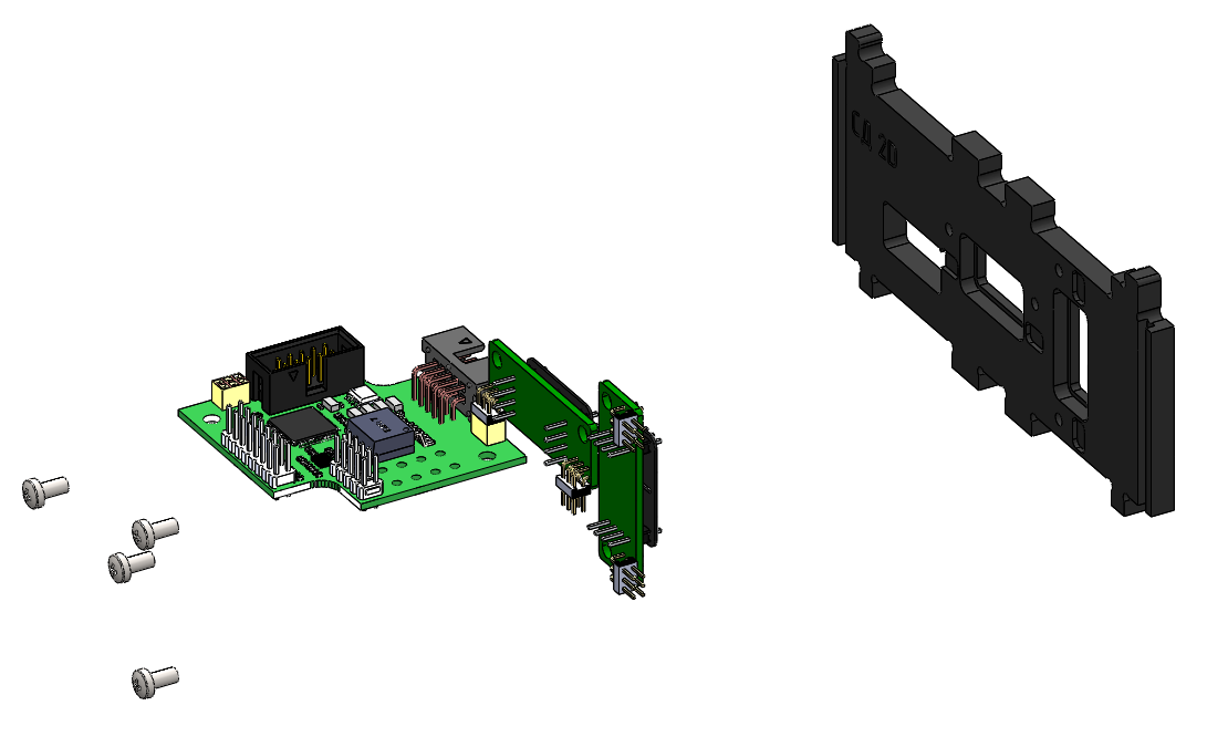
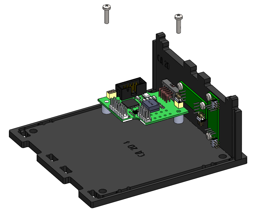
3) Insert the connector of the universal board into the cutout of the side wall and fix the solar sensor board with M3x6 screws (Picture 4):
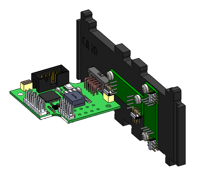
Picture 4. Mounting of the universal board with a side wall
4) Install white plastic washers on the lower base (marked: SS ↓) (Picture 5):
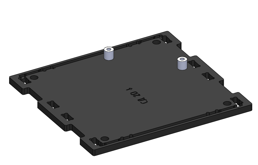
Picture 5. Installing washers on the lower base
5) Fix the board with the side wall on the bottom base. To do this, position the projections of the side wall with holes in the base and snap them. Fix the board with M3x12 screws with a cylindrical head, holding the plastic washers (Picture 6):
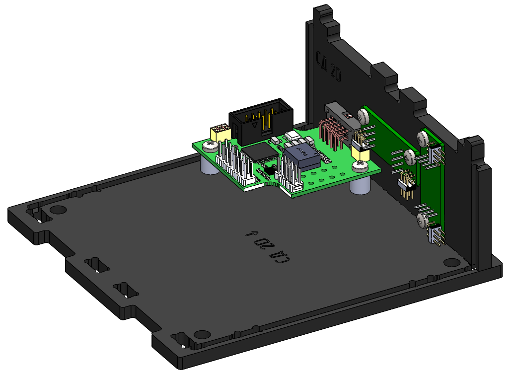
Picture 6. Side wall mounting
6) Fix the second side wall on the lower base. To do this, position the projections of the side wall with holes in the base and snap (Picture 7):
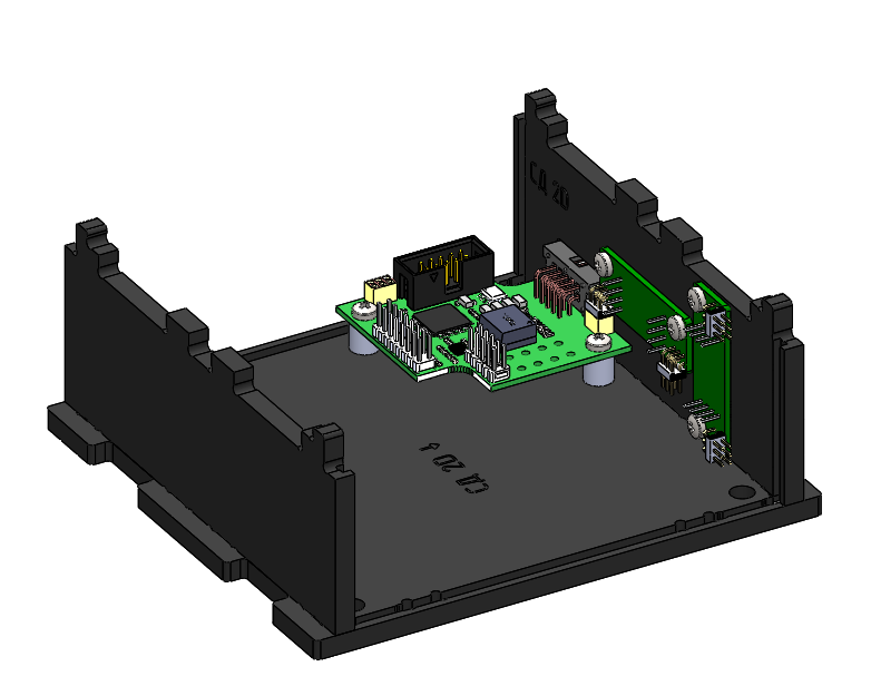
Picture 7. Fixing the second side wall
7) Connect the vertically mounted solar sensor board to the universal board.
8) Fix four windows on the bottom base. To do this, hold each window along the guides in the walls to the base and snap it. Observe the location and orientation of the window with axes as in the figure below (Picture 8):
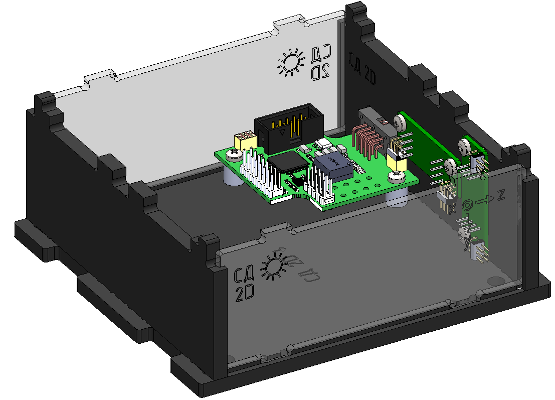
Picture 8. Fixing the side windows
9) Attach the top cover (marked SS↑) to the assembled housing. To do this, position the cutouts on the top cover and the protrusions of two walls and four windows and snap them with effort.
This is what the assembled SS module looks like (Picture 9):
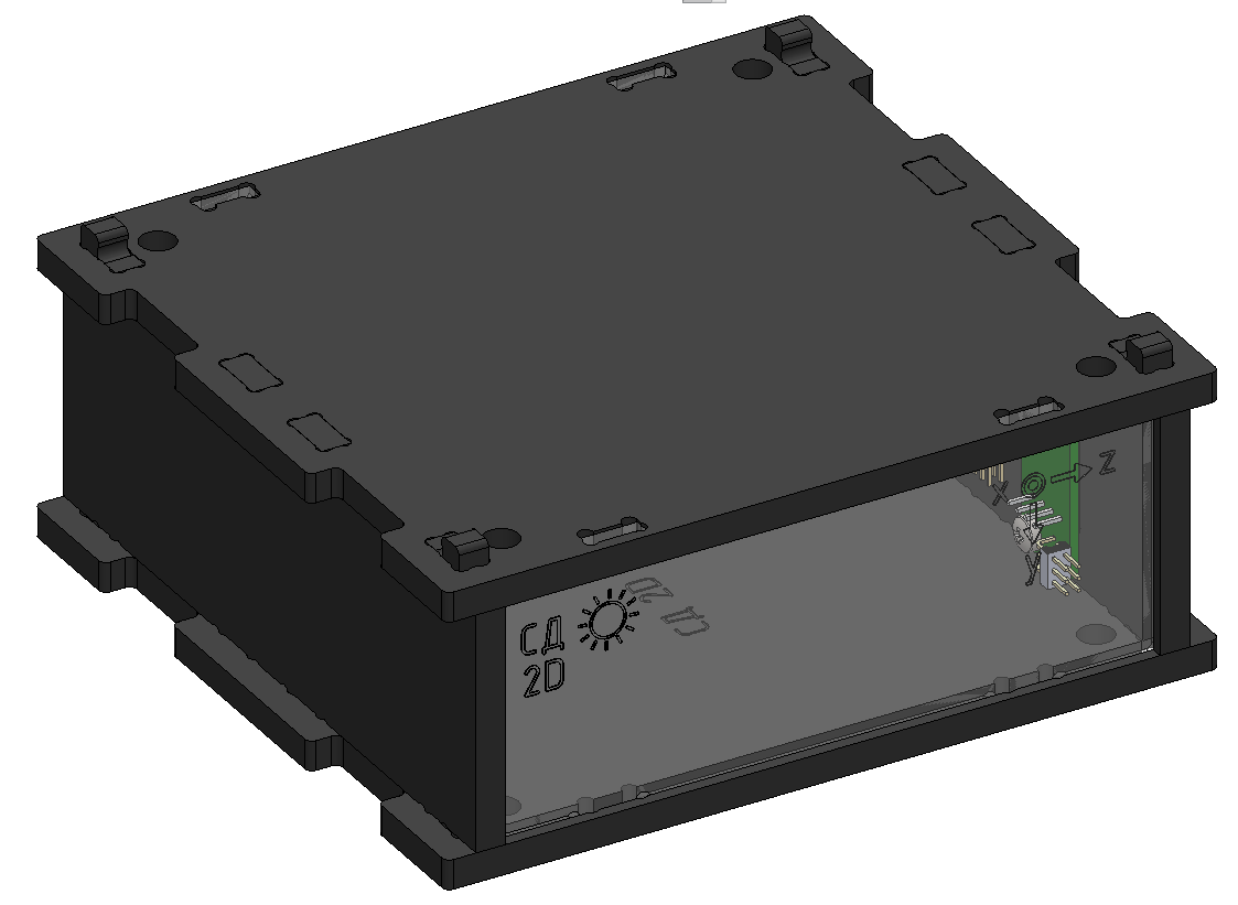
Picture 9. Assembled SS module