Assembly of RW 3D (reaction wheel control motors for three-axis configuration)
The RW 3D module contains three control reaction wheel motors arranged in accordance with the x, y and z axes of the magnetometer. This allows the satellite designer to rotate around the center of mass while working out the orientation and stabilization system. To solve this problem, a semi-natural modeling stand is used, consisting of three closed circuits (coils) located in three planes with a platform on which the satellite constructor is placed.
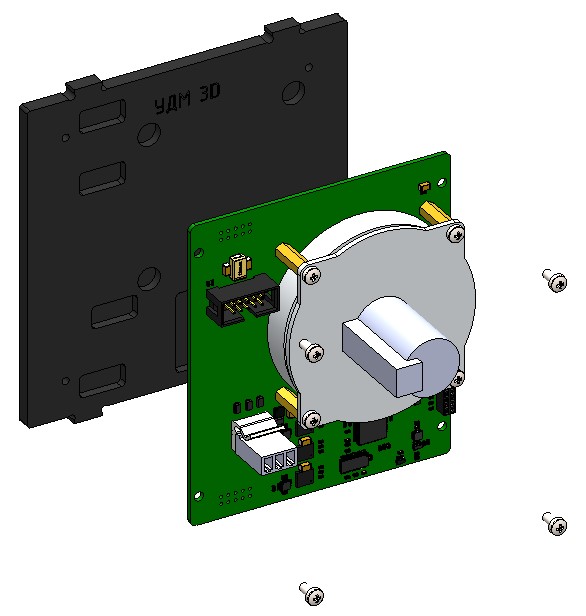
Components required for assembly (Picture 1):
- all parts labeled RW 3D (two bases, three walls, two transparent walls);
- reaction wheel block with board – 3 pcs;
- cable for connecting reaction wheel boards – 1 piece;
- fasteners (screws with a cylindrical head M3x6 - 14 pcs.).
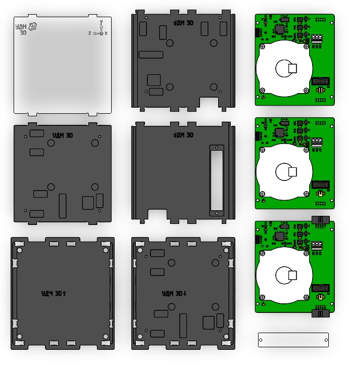
Picture 1. Components for module assembly
Assembly order
Addresses A, B and C. are indicated on the control motor-reaction wheel boards. Observe their correct location inside the module. Install reaction wheel A on the rear wall of the module, reaction wheel B on the lower base of the module and reaction wheel C on the side wall
1) On the lower base (indicated: RW 3D ↓) install the board with a reaction wheel (side connectors are soldered on the board), securing it with M3x6 screws with a cylindrical head (4 pcs) (Picture 2):

Picture 2. Installing the reaction wheel board on the lower base
2) Attach a second board with a reaction wheel to the side wall using M3x6 cylindrical head screws (4 pcs) (Picture 3):
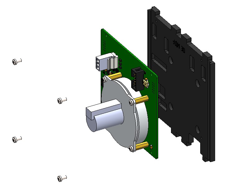
Picture 3. Installing the reaction wheel board on the side wall
3) Install the side wall on the lower base. To do this, combine the projections of the side wall with the holes in the base and snap (Picture 4):
Picture 4. Installing the side wall to the bottom base
4) Attach a transparent panel to the side wall using M3x6 cylindrical head screws (2 pcs) (Picture 5):
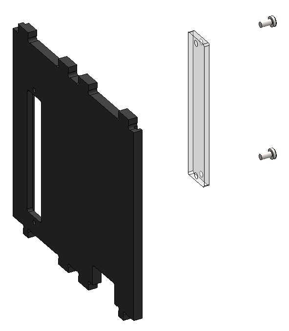
Picture 5. Mounting the transparent panel to the side wall
5) Install the side wall on the lower base. To do this, align the projections of the side wall with the holes in the base and snap (Picture 6):
Picture 6. Installing the side wall to the bottom base
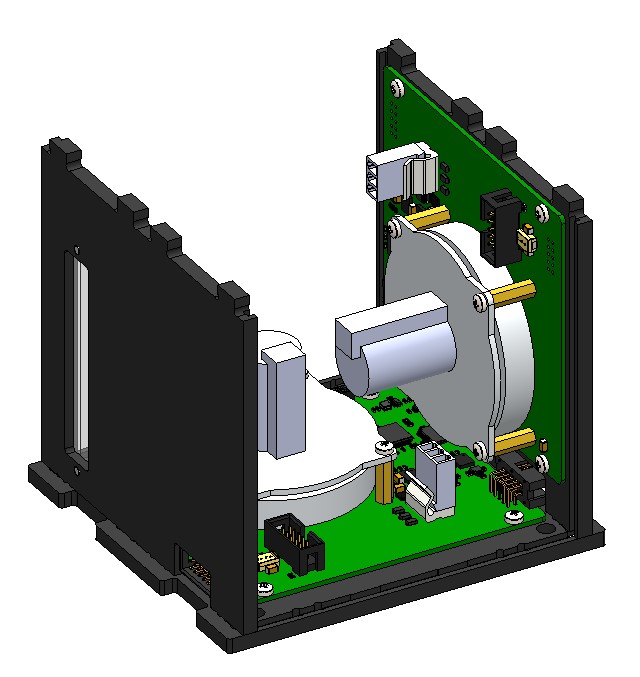
6) Attach a third board with a reaction wheel to the side wall using M3x6 cylindrical head screws (4 pcs) (Picture 7):
Picture 7. Mounting the reaction wheel board to the side wall
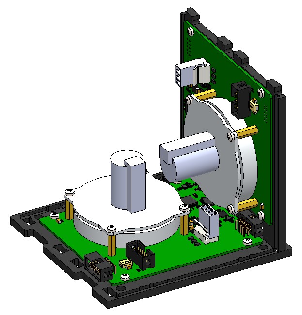
7) Install the side wall on the lower base. To do this, combine the projections of the side wall with the holes in the base and snap. Connect the three boards to the reaction wheels with a loop (Picture 8):
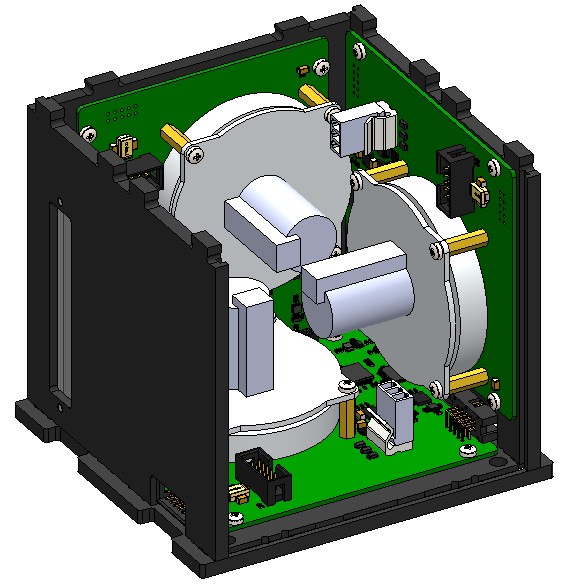
Picture 8. Installing the side wall to the bottom base
8) Fix the transparent panel on the bottom base. To do this, run the panel along the guides in the walls to the base and snap it. Observe the location and orientation of the transparent panel with axes as in the picture below (Picture 9):
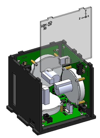
Picture 9. Installing a transparent panel
9) Attach the upper base (marked RW 3D↑) to the assembled housing. To do this, combine the cutouts on the upper base, the protrusions of two walls and two transparent panels, and snap them with effort.
This is what the assembled RW module looks like (Picture 10):
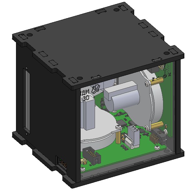
Picture 10. The assembled module