Assembly of the loop tester
The loop tester is a module that checks the operation of compressed cables. If the cables are compressed correctly, the indicator on the module turns green, otherwise it turns red.
Components required for assembly (Picture 1):
- All parts labeled Tester (two bases, two walls, two transparent panels);
- additional details (transparent panel with cutouts);
- Loop tester board;
- fasteners (brass racks PCHSS M3x10 – 4 pcs., countersunk head screws M3x10 – 8 pcs., cylindrical head screws M3x6 – 4 pcs.).
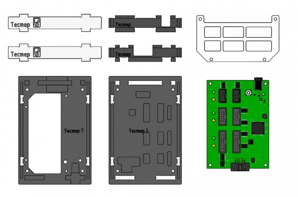
Picture 1. Components for module assembly
Assembly order
1) Install two side walls on the lower base (marked: tester ↓). To do this, combine the projections of the side walls with the holes in the base and snap (Picture 2):
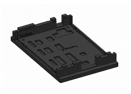
Picture 2. Installation of side walls
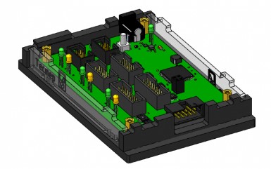
2) Install the tester board (Picture 3):
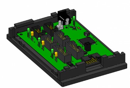
Picture 3. Installing the tester board
3) Attach the board to the bottom base using four brass PCHSS M3x10 racks and four countersunk head screws M3x10 (Picture 4):
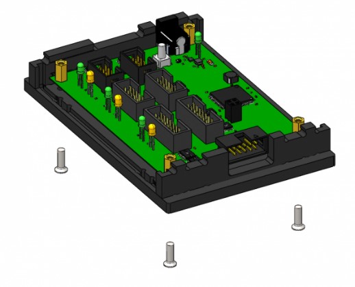
Picture 4. Fixing the lower base
4) Fix two transparent panels on the bottom base. To do this, hold each panel along the guides in the walls to the base and snap (Picture 5):
Picture 5. Mounting of two panels
5) Assemble the upper base (marked: tester ↑) with a transparent panel with cutouts using M3x6 cylindrical head screws (Picture 6):
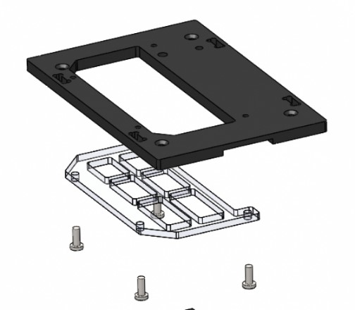
Picture 6. Assembly of the upper base
View of the assembled upper base from below (Picture 7):
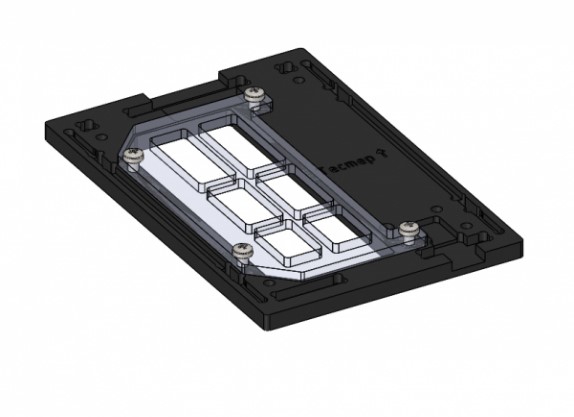
Picture 7. The base is assembled
6) Install the top cover on the assembled housing. To do this, combine the cutouts on the top cover, the protrusions of two walls and two transparent panels, and snap them with effort (Picture 8):
Picture 8. Installing the top cover
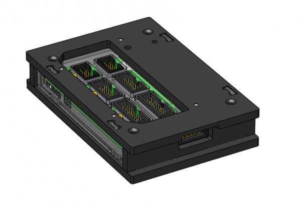
7) Attach the top cover with four M3x10 countersunk head screws. This is how the assembled module "Loop Tester" looks like (Picture 9):
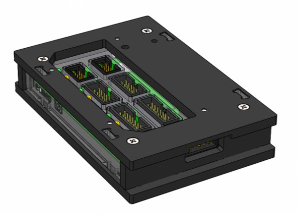
Picture 9. Assembled module