Cable network assembly
About the cable network
The on-board cable network is necessary for information exchange between the subsystems and the central computer, as well as for supplying power to the subsystems. Satellite subsystems have several redundant connectors for connection to the on-board network. Thus, the device connected to the on-board network is not only available for information exchange with it, but also provides the opportunity to connect subsequent subsystems in the circuit through itself. The information network is built using the UniCAN protocol. To facilitate installation, the power lines and the information network are combined into one loop. The subsystems are connected via the connector IDC-10F (DS1016-10) on the wiring harness side and IDC-10M (DS1013-10) on the device side. Since different layout of the designer elements is possible, the determination of the length of each loop, its configuration, and ultimately the manufacture remains with the user.
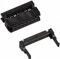
IDC-10F connector (Picture 1):

Picture 1. IDC-10F connector
A wide cable with connectors of type IDC-14F (DS1016-14) is used to connect the OBC to the camera adapter.
IDC-14F connector (Picture 2):
Picture 2. IDC-14F connector
A narrow cable with connectors of type IDC-6F (DS1016-06) is used to connect OBC and HF.
IDC-6F connector (Picture 3):

Picture 3. IDC-6F connector
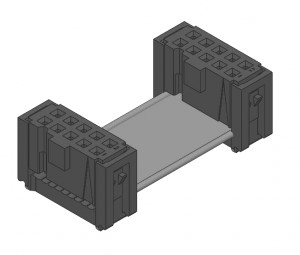
10 pin cable (Picture 4):

Picture 4. 10 pin cable
Preparation
- From the OrbiCraft 3D kit, take: a crimper, wire cutters, a loop coil, 2 connectors IDC-10F, a loop tester and a 12V power adapter.
- Cut the cable of the required length from the coil of the ten-channel loop with scissors.
Assembly of the loop
Insert the yellow insert included in the kit into the crimper.
Place the connector in the yellow insert under the center of the crimper clamping bar.
Holding the crimper with the connector with one hand, place the end of the cable into the connector with the other hand.
Use the crimper to clamp the connector with the inserted end of the cable until a characteristic click sounds.
Make sure visually that the connector is locked.
tipMake sure that the cable is completely in the connector, but does not stick out too much on the back side.
Before making an effort to snap, press the latch slightly, make sure that the cable cores fall evenly between the contacts and only then finally snap the connector.
Repeat the procedure for the second end of the cable with the second connector IDC-10F.
When crimping the cable, it is important to remember that the installation directions of the connectors coincide, as shown in the illustrations below.
Correct assembly (Picture 5):
Picture 5. Correct assembly
Incorrect assembly (Picture 6):

Picture 6. Incorrect assembly
The existing pinout of the connector (the purpose of each of the contacts) minimizes the likelihood of damage to the equipment if the cable is improperly manufactured by the user. However, it does not guarantee that the device cannot be disabled in principle. It should also be noted that the manufacture and refinement of loops by the user does not require special skills and tools.
Connecting the constructor modules (Picture 7):
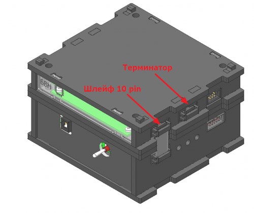
Picture 7. Connecting the constructor modules
When assembling the cable network, be sure to install a termination resistor (terminator) in one of the empty connectors.
Terminating resistor (terminator)
A terminator, an energy absorber (usually a resistor) at the end of a long line, whose resistance is equal to the wave resistance of this line. In relation to electronics, the word "terminator" is used mainly in computer jargon, a synonym is the expression "matched load". A 120 ohm terminator is installed for the CAN bus (Picture 8):

Picture 8. Terminating resistor (terminator)
Checking the loop
- Connect the loop tester to a 220V network using the supplied 12V power adapter.
- Plug the assembled cable into the appropriate connectors on the cable tester. The green light "OK" should light up.
If you have a red light "Short circuit", it means either you damaged the insulation of two adjacent channels when compressing the loop, or you incorrectly placed two connectors relative to each other. Try to re-compress the cable by following the instructions above.