SS module assembly (solar sensors)
A solar sensor is a sensor that allows you to determine the source of sunlight. The SS module has four solar sensors that allow OrbiCraft 3D to receive telemetry and use a flywheel control motor to deploy it depending on the angle at which the sunlight source is located in relation to OrbiCraft 3D.
Components required for assembly (Picture 1):
- all parts labeled SS (two bases, two walls, two brackets, four transparent panels);
- boards (universal board – 1 pc, solar sensor board – 4 pcs);
- fasteners (screws with a cylindrical head M3x6 – 12 pcs.).
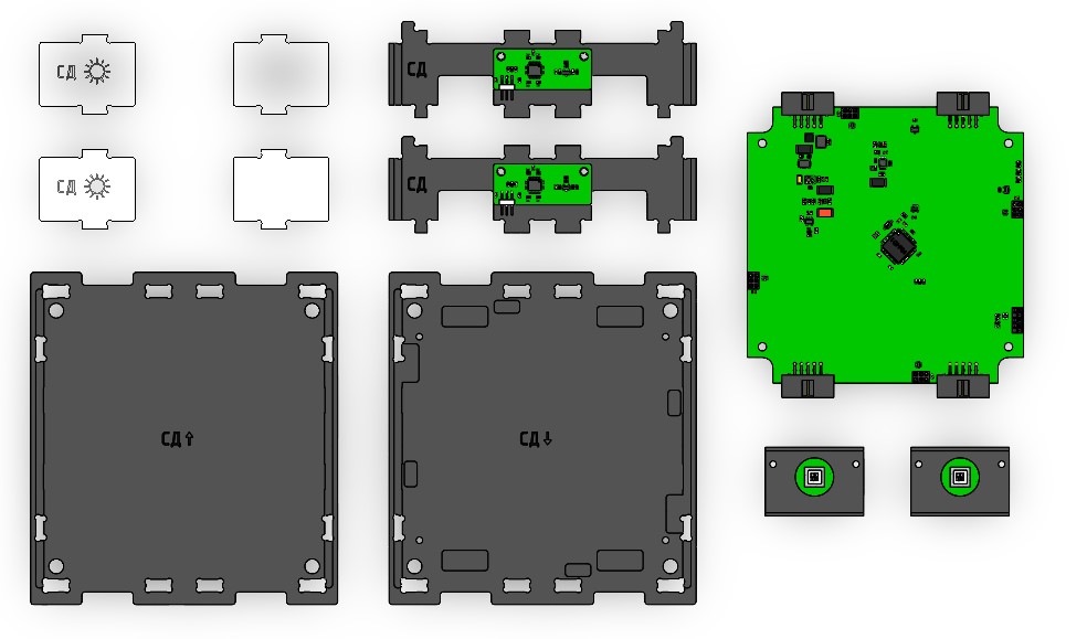
Picture 1. Components for module assembly
Assembly order
1) Install a universal board on the lower base (marked: SS ↓), fix the board with four M3 x 6 screws with a cylindrical head (Picture 11):
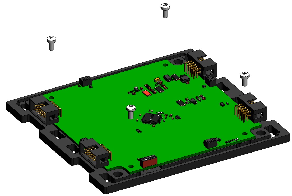
Picture 2. Installing the board
The numbers of the solar sensors are indicated on the back of the sensor.
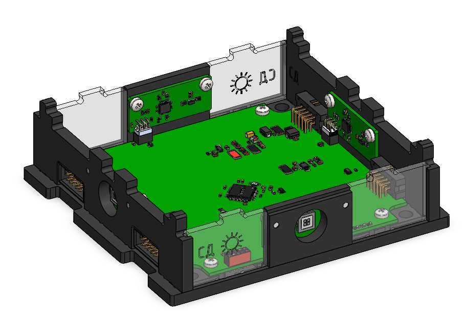
2) Screw the solar sensor boards No. 1 and No. 3 to the side walls with two M3x6 screws on each side. The resulting walls are connected to a universal board, following the designations on it: Sensor 1 and Sensor 3, respectively. To do this, combine the projections of the side walls with the holes in the base and snap them. In this case, the connectors of the solar sensors must be connected to the connectors of the universal board (Picture 3):
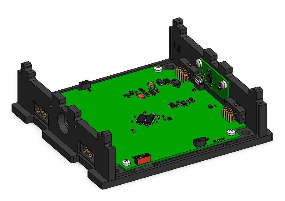
Picture 3. Connection of the solar sensor board to the universal board
3) Screw the solar sensor boards No. 2 and No. 4 to the brackets with two M3x6 screws on each side and connect to the universal board. To do this, align the protrusions of the brackets with the holes in the base and snap them. At the same time, connect the connectors of the solar sensors to the connectors of the universal board in the Sensor 2 and Sensor 4 locations, respectively (Picture 4):
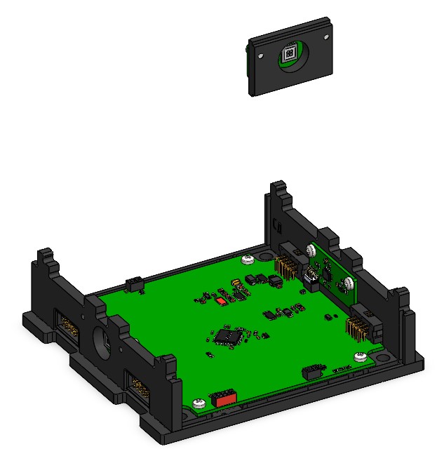
Picture 4. Connection of the solar sensor board on the bracket to the universal board
4) Fix the four transparent panels on the bottom base. To do this, hold each panel along the guides in the walls to the base and snap it. Please note that the panel with the coordinate system applied to it should be located on the side of the solar sensor No. 2 (Picture 5):
Please note that the panel with the coordinate system applied to it should be located on the side of the solar sensor No. 2.
Picture 5. Mounting of transparent panels
5) Attach the top cover (marked SS↑) to the assembled case. To do this, combine the cutouts on the top cover, the protrusions of two walls and four panels and snap them with effort.
This is how the assembled SS module looks like: (Picture 6):
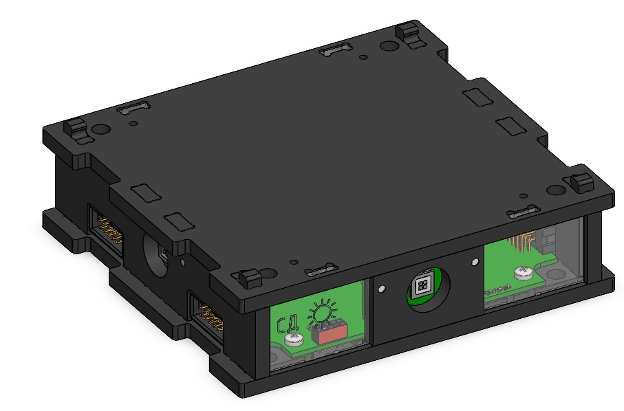
Picture 6. Assembled SS module