Bringing the OrbiCraft 3D satellite designer's devices to a single coordinate system
In order for the BVM to correctly calculate the orientation of the OrbiCraft 3D satellite designer and correctly control the orientation, the readings of all on-board instruments should be brought to some single coordinate system. This coordinate system is the construction coordinate system of the OrbiCraft 3D satellite constructor. It coincides with the coordinate system of the BVM module (on-board computing module). A magnetometer and an angular velocity sensor are installed on this module. The flywheel unit and the solar sensor have their own coordinate systems - instrument ones, the direction of the axes of which do not coincide with the building coordinate system. In order to bring the readings of the instruments to a single coordinate system, it is required to give the BVM information about exactly how the sensors and flywheels are located on the body of the designer. To do this, you need to create a matching matrix (or “installation matrix”) of the flywheel unit and solar sensors. As a rule, the module axes of the same name in the constructor are located either at an angle of 90 ° or 180 °. Accordingly, the values of the elements of this matrix will be -1, 0 or 1.
The installation matrix is compiled separately for each block (except for the PN block) and recorded in the BVM memory. For the OrbiCraft 3D designer, we will get two matrices – one for the solar sensor module, the other for the flywheel block.
Let's see what the coordinate system looks like for the constructor and solar sensors, where OXcYcZc is the construction coordinate system, and OXYZ is the instrument coordinate system of the solar sensor. Let's take the coordinate system of the BVM module as a building coordinate system (Picture 1):
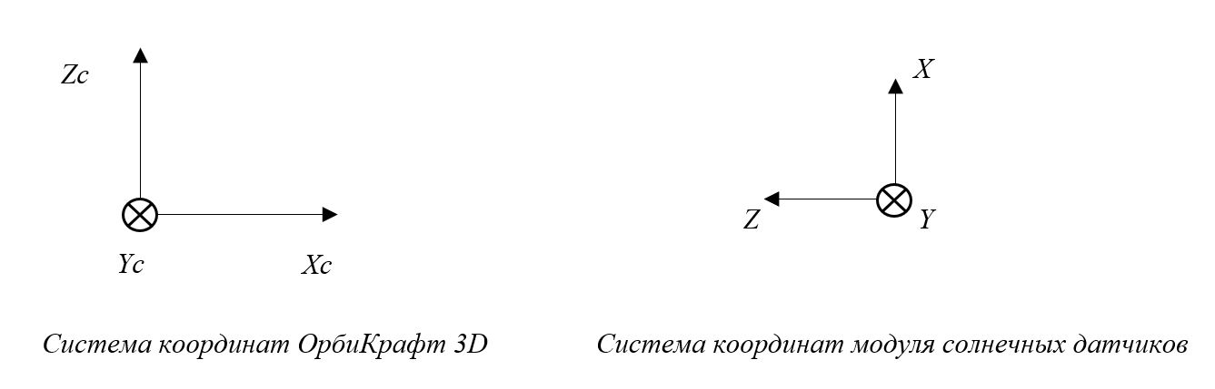
Picture 1. Coordinate systems of BVM and SD modules
To bring the readings of the solar sensor module to a single coordinate system of the designer, a 3x3 matrix should be compiled. To do this, we superimpose the coordinate axes of the SD and BVM modules on top of each other. Matrix Rows:
- The first row is the X–axis.;
- The second line is the Y–axis.;
- The third line is the Z–axis construction.
When the axes are superimposed, the Xc axis coincides with the Z axis of the SD module, directed in the opposite direction. Therefore, the first row of the matrix takes the form (0 0 -1). The direction of the Y axis of the designer and the Y axis of the solar sensor module coincide, therefore, the second row of the matrix takes the values (0 1 0). The Zc axis of the constructor coincides in the direction with the X axis of the SD module, therefore, the third row of the matrix has the form (1 0 0). As a result, we get a matrix of the form:
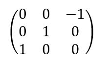
In fact, the coordinates of the ort vectors of the axes of the instrument coordinate system obtained in the construction coordinate system are recorded in the rows of the correspondence matrix.
The flywheel does not have a three-dimensional coordinate system, but only a guiding vector, the direction of which coincides with the direction of the axis of rotation of the flywheel. Therefore, to bring it to a single system, we will get a vector. In three-axis OrbiCraft 3D, three flywheels form a three-dimensional coordinate system. The "Gimlet Rule" is used to determine the guiding vector. The flywheel vector is positioned as follows (Picture 2):
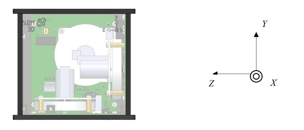
Picture 2. The coordinate system of the flywheel block
For a flywheel with index 0, the direction of the vector is the X axis, for a flywheel with index 1 – the Y axis, for a flywheel with index 2 – the Z axis.
When the coordinate systems of the BVM module and the flywheel block are superimposed, we obtain that:
- The X axis of the flywheel block coincides with the Yc axis of the BVM module, but have a different direction. Therefore, we get the vector {0 -1 0} (for a flywheel with index 0);
- The Y axis of the flywheel block coincides with the Zc axis of the BVM module. Therefore, we get the vector {0 0 1} (for a flywheel with index 1);
- The Z axis of the flywheel block coincides with the Xc axis of the BVM module. Therefore, we get the vector {-1 0 0} (for a flywheel with index 2).
Sending a command to the solar sensor in the Houston Application
After receiving the matrix, you need to go to Houston Application and select the command 5-F042 set_ss_inst_matrix and enter data from the matrix, where index is the number of the solar sensor. Orbicraft 3D has one solar sensor, therefore, its index is 0 (Picture 3):
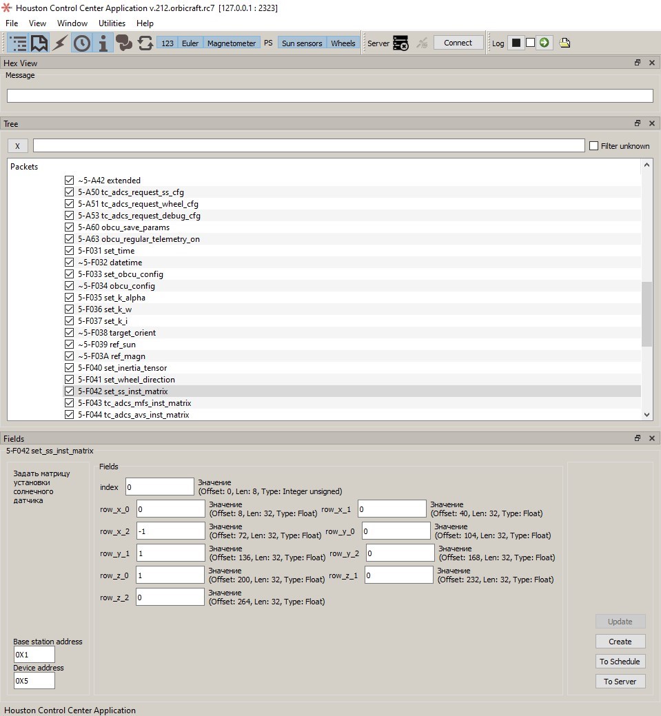
Picture 3. Entering the coefficients of the matching matrix for the SD in the Houston Application
Sending a command to the flywheels in the Houston Application
Select the command 5-F041 set_wheel_direction. Specify the index of the flywheel accessed by the Houston Application – 0, 1 or 2. Enter the data obtained from the calculation of the coordinate system vector (Picture 4):
- Index 0: x=0, y=-1, z=0;
- Index 1: x=0, y=0, z=-1;
- Index 2: x=-1, y=0, z=0.
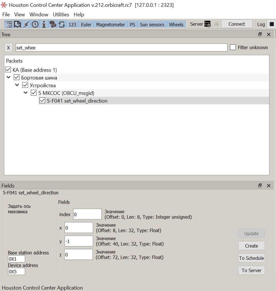
Picture 4. Data entry of the matching matrix for the flywheel block in the Houston Appication