Setting up the Houston App
Setting up the period for receiving telemetry
It is necessary to set the period for receiving telemetry from all devices to 100 milliseconds. Use the -A63 cfg_regular_telemetry command that all devices have (Picture 1):
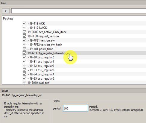
Picture 1. The telemetry acquisition setup command
If necessary, turn on the telemetry of the solar sensors with the command -23 tc_enable_telometry (Picture 2):
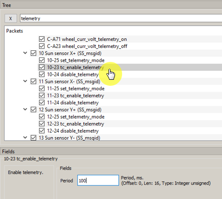
Picture 2. Solar sensor telemetry period
Save the settings of the solar sensors using the command 10-A60 cfg_save_params, the response to this command will be ~ACK.
Setting the offset of the zero DUS
Set the offset to zero by using the 9-BD1 set_ratesens_offset command. Install OrbiCraft 3D on the arrestor so that it is stationary and remember the values of deviation from zero of the DUS readings. In the boxes of the Fields field, enter these DUS values to compensate for them (Picture 3):
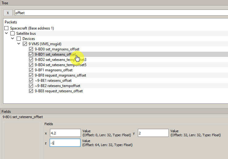
Picture 3. Setting the zero offset
The value of the zero offset should be no more than 0.2.
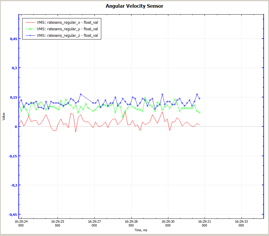
Picture 4. Graph of DUS values
Save the DUS settings using the command 19-A60 cfg_save_params, the response to this command will be ~ACK.
Setting the zero offset of the magnetometer
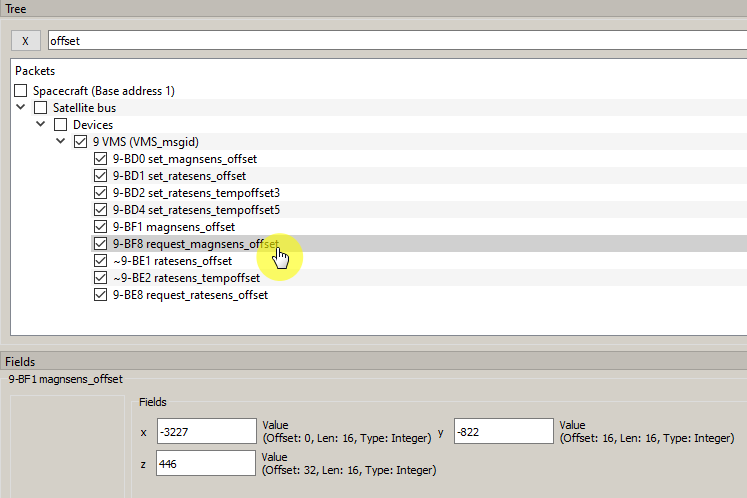
Picture 5. Setting the zero offset of the magnetometer
Setting up the orthonormalization matrix
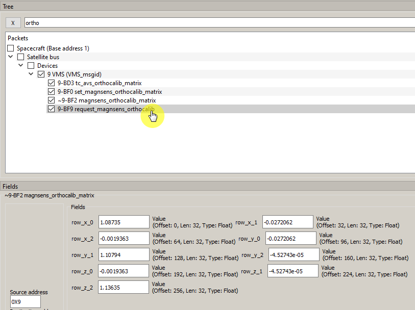
Picture 6. Orthonormalization matrix
Request for extended telemetry
Request extended telemetry with the command 5-A41 request_extended_telemetry (Picture 7):
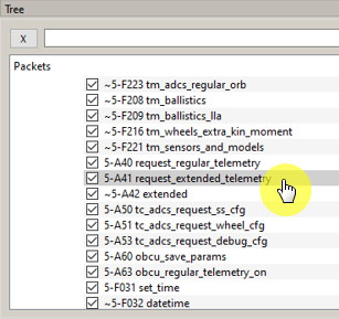
Picture 7. Request for extended telemetry
In response to the request, 12 responses will be received (Picture 8):
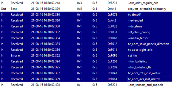
Picture 8. Responses to the requested telemetry
In the History window, select the 5-F033 set_obcu_config command. All parameters should be the same as in Figure 9.
Important fields K_alpha=3, K_w=5, angular_rate_multiplikator=5, wheel_num=3, wheel_control_limit=0.01, wheel_rotor_inertia=8.4e-05 (Picture 9):
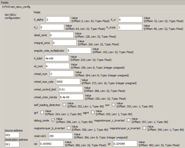
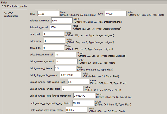
Picture 9. Parameters of the selected command
If necessary, adjust the parameter and click on the To server button to save the parameters.
Checking the solar sensors
Requesting the configuration of solar sensors with the command 5-A50 tc_adcs_request_ss_cfg (Picture 10):
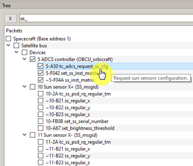
Picture 10.SD configuration request
In response, we will receive the message ~5-F04A ss_inst_matrix (Picture 11):
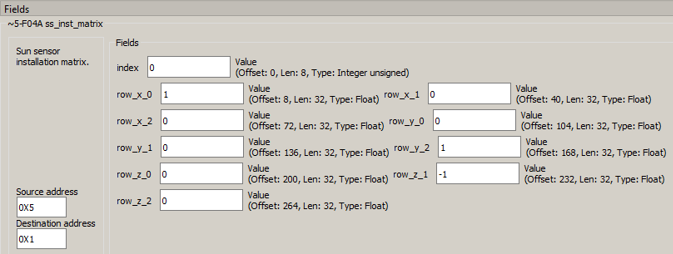
Picture 11. The received message
Checking the flywheels
Requesting the configuration of the flywheels 5-A51 tc_adcs_request_wheel_cfg (Picture 12):
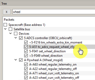
Picture 12. Flywheel configuration Request
We will get three answers 5-F049 wheel_direction. With index 0 - flywheel A, with index 1 - flywheel B, with index 2 - flywheel C (Picture 13):
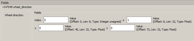
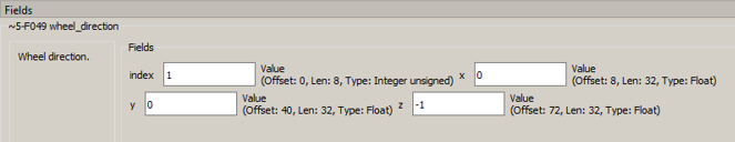
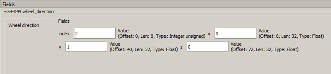
Picture 13. The responses received
Turn on the flywheels one at a time. Set the rotation speed of the flywheel A to 200 rpm with the command A-A01 rpm (Picture 14):
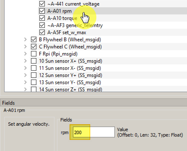
Picture 14. Setting the rotation speed of the flywheel
It is necessary to check which flywheel has started to rotate and in which direction. The flywheel A must rotate in the direction of the "right screw".