Assembly of the UHF+HF+ERS module (Earth remote sensing)
The Earth remote sensing module is a module that includes a camera, an on-board UHF (ultra-short waves) and HF(high-frequency) transceiver. Using the camera, a picture is taken, which is saved in the Raspberry Pi CM, and transmitted to the MCC via HF (imitation of the X-band of frequencies), UHF (435...437 MHz) or a Wi-Fi module. The UHF module also allows you to receive telemetry from the satellite constructor in the Houston Application program without connecting via a Wi-Fi connection.
Components required for assembly (Picture 1):
- all parts labeled ERS (two bases, two walls, two transparent panels), camera bracket;
- Boards (UHF board, HF board, camera, camera adapter board);
- antenna;
- fasteners (screws with a cylindrical head M3x6 – 7 pcs., M2x6 – 6 pcs.).
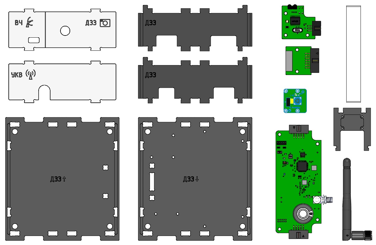
Picture 1. Components for module assembly
Assembly order
1) Install the UHF board on the lower base (marked: ERS ↓), fix it with M3x6 screws with a cylindrical head (Picture 2):
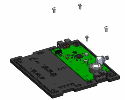
Picture 2. Installing the UHF board
2) Connect the antenna to the UHF board (Picture 3):
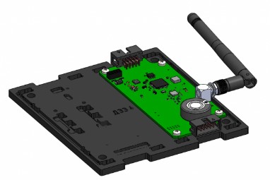
Picture 3. Installing the antenna
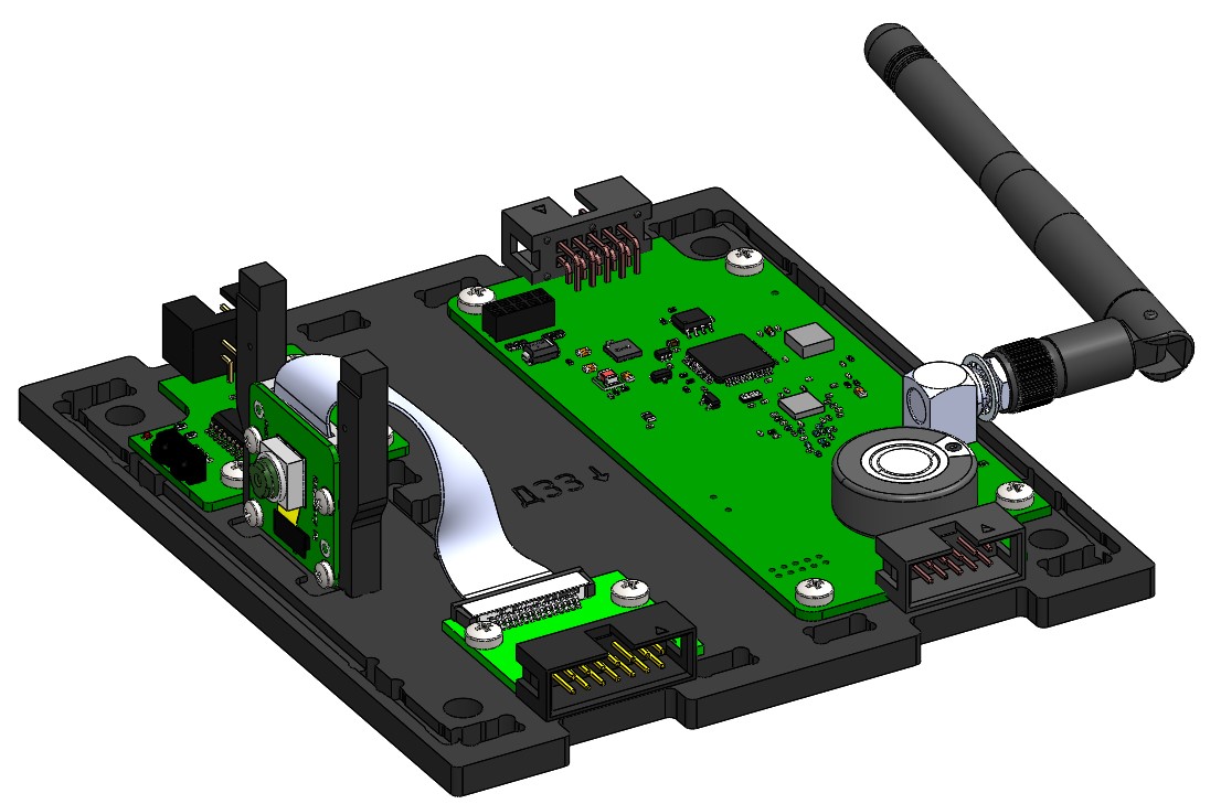
3) Install the HF board on the lower base, fix it with M3x6 screws with a cylindrical head (Picture 4):
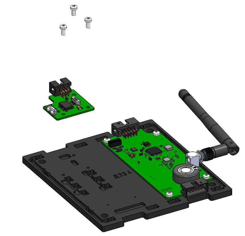
Picture 4. Installing the HF board
4) Assemble the camera with the bracket using four M2x6 screws (Picture 5):
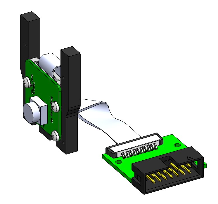
Picture 5. Camera Assembly
5) Mount the camera bracket on the base. To do this, position the protrusions of the bracket with holes in the base and snap them. Install the adapter board on the lower base, fix it with M2x6 screws with a cylindrical head. The camera and the adapter board are connected by a cable. (Picture 6):
Picture 6. Installing the camera on the base of the module
6) Install the side walls. To do this, align the projections of the side walls with the holes in the base and snap (Picture 7):
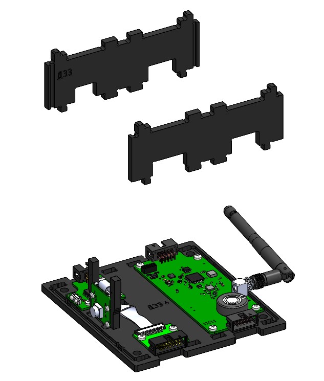
Picture 7. Installation of side walls
7) Fix two transparent panels on the bottom base. To do this, run the panels along the guides in the walls to the base and snap them (Picture 8):
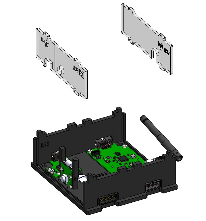
Picture 8. Installing transparent panels
8) Attach the top cover (marked: ERS) to the assembled housing. To do this, combine the cutouts on the top cover, the protrusions of two walls and two panels, and snap them with effort (Picture 9):
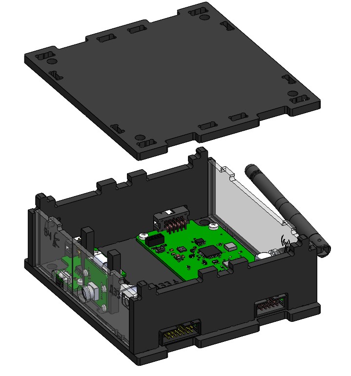
Picture 9. Installing the top cover
This is how the assembled UHF+HF+ERS module looks like (Picture 10):
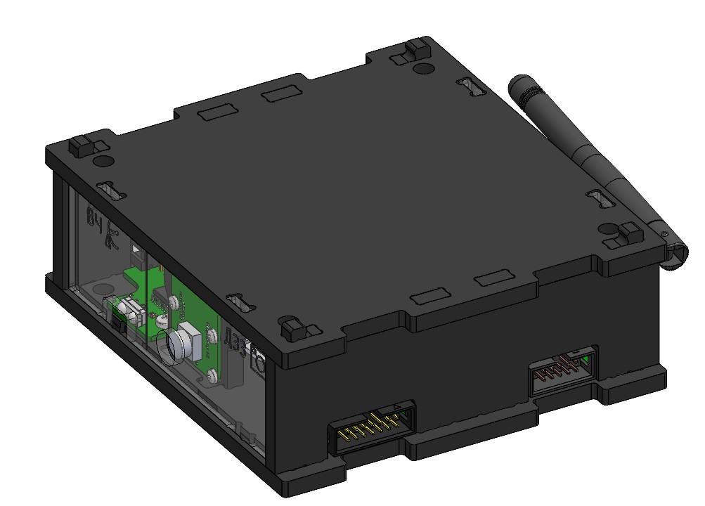
Picture 10. The assembled module