Terra Space Environment Simulator Complex
Earth's magnetic field simulator
Simulator of the Earth's magnetic field is a magnetic coil designed to create a controlled magnitude of the magnetic flux directed through its vertically mounted plane (working plane). Such a frame plays the role of a simplified uniaxial simulator of the Earth's magnetic field (Picture 1):

Picture 1. Current frame
The current frame is installed on the floor and provides the possibility of placing the OrbiCraft 3D designer on the thread so that its center of mass is placed in the working plane – the equatorial plane of the globe, at a height of about 80 cm from the floor, and its unlimited free rotation is ensured.
Main Features:
- The uniformity zone (5%, 1 degree) coincides with the size of the constructor;
- Material: aluminum frame, copper conductor;
- Dimensions: provide free rotation of the layout inside it on a string with the possibility of height adjustment by ± 5 cm;
- Continuous operation time at full power: at least 4 hours;
- Supply voltage: no more than 27 V;
- Safe for laboratory use.
Earth Simulator
Earth Simulator (Picture 2) - an Earth globe that provides:
- a geometrically scaled appearance of the Earth, visible from a satellite, with a diameter of 130 cm;
- the kinematics of satellite movement along the subsatellite path along the equatorial orbit - either in real time, or using reasonable scaling (acceleration, time dilation), the conditions for shooting certain areas of the surface are similar and in the same terms as shooting the real Earth's surface by remote sensing satellites (time, orbital parameters, point coordinates, region coordinates);
- conditions of communication with the "ground" (ground measuring points – NPCs) via telemetry and telecommand radio lines, when the ground point is in the zone of geometric radio visibility of the board, the LEDs of the corresponding "ground station" turn on;
- conditions for transmitting data "to the ground" via a high-speed communication channel when the ground station is in the zone of geometric radio visibility of the board. Earth Simulator

Picture 2. Terra Earth Simulator
The satellite "flies in near-Earth orbit", and in fact - hangs on a thread in a simulated "geomagnetic" field (inside the current frame) and rotates horizontally on the thread - either freely or under the action of an on-board control system programmed by the user - while the globe of the Earth in front of it rotates evenly, simulating the movement of the device in an equatorial orbit. The area of the globe surface required for shooting in the area of the equator of the globe sooner or later turns out to be in front of a hung device, and the task of the satellite control system is to orient and stabilize the satellite on the suspension by this moment, directing the camera's field of view with the necessary accuracy to the area of interest, remove it and then transfer the shooting data "to the Ground" to the user, accompanying this the ability to orient the laser pointer to the required "ground" reception point.
The Globe is controlled via the USB port of a PC, whose tasks include controlling the rotation of the globe, as well as managing a network of "ground" (on the surface of the globe) telemetry reception and processing centers (NIPS), as well as "surface" centers for receiving high-speed information. These centers are located on the surface of the "Earth" in pre-known, predetermined and time-invariant geographical points.
The conditions of communication with the "Earth" via telemetry and telecommand radio lines are simulated by calculating when one or another NPC on the surface of the globe is in the zone of geometric radio visibility with a side suspended on a string, and issuing the appropriate command to turn on or off the radio receiver of this ground station. After switching on, the ground station is in the telemetry data reception mode by default.
Conditions for transmitting data from the board to the "Earth" (photodetector on the surface of the globe) over a high-speed communication channel, they are simulated using the illumination and holding of the pointer of a given marker on the surface of a rotating globe by an on-board laser beam. The fact that the photodiode is illuminated on the surface of the globe for a given time interval is a sign of the normal orientation of the "board" to the "Ground", after which data from the board is transmitted over a regular Wi-Fi channel all the time while the LED of the RF transmitter illuminates the necessary marker.
The main characteristics of the globe:
- diameter 130 cm;
- the weight of the entire simulator (globe and hidden drive with control system) is 40 kg;
- the weight of the globe is 20 kg, the material of the globe is durable fiberglass;
- Good contrast coverage of the globe;
- a map with a view of the Earth from space and a grid of parallels and meridians;
- vertical axis of rotation of the globe;
- the rotation speed of the globe can be smoothly or stepwise adjusted from the PC from 0 to 1 rpm, the maximum error in maintaining the rotation speed is no more than +-2%; at the tournament, the rotation speed will be set to 0.2 rpm;
- all drives, electronics, etc. are located inside the globe;
- The globe is connected to a 220V outlet and to the USB port of the control PC.
Characteristics of the globe control system:
- single-axis electric drive;
- Drive driver and driver control board;
- connecting to a computer via the USB interface;
- a control system for "ground" telemetry points, as well as a photodiode for detecting the light of a laser pointer "board".
All geometric parameters of the globe, kinematic parameters of its rotation are consistent with the capabilities of the dynamic onboard control system of the satellite layout (speed, accuracy, number of degrees of freedom, continuous operation time), as well as with the capabilities of the onboard payload (field of view, exposure time, illumination conditions, data transfer rate) used as part of the layout to obtain special information.
Sun Simulator
The Sun Simulator
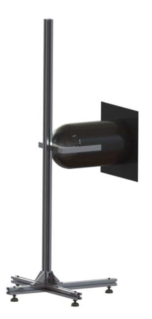
Picture 3. Sun Simulator
Sun simulator is a light source that provides a beam of light, similar in a number of characteristics to the solar one, in order to affect the orientation system of the layout, as well as the conditions for shooting areas of the globe with a camera installed as part of the satellite layout (Picture 3).
The main parameters of the simulator:
- the non-parallelism of the beam is not worse than 12 degrees;
- the radiation spectrum is as close as possible to the solar one;
- the diameter of the light beam concentrating 90% of the power, no more than 20 cm;
- the power of visible radiation is close to Solar 1367 W/m2 at a distance of at least 0.2 m from the light source;
- eye safety (protection in the form of glasses);
- during the experiment, the simulator is stationary, and can be easily moved by one person to any distance between experiments;
- powered by a regular 220 V mains;
- the presence of a mounting system (tripod), which allows for smooth adjustment of the light source in height (from 0.5 to 1.5 m), in the angle of inclination to the horizon (-60..60 degrees).
The Sun simulator must be turned on by the user before starting the experiment and turned off after conducting the experiment manually using a conventional switch.