The complex of space environment simulators "Terra 2.0"
Purpose
The Terra2.0 complex is a set of simulators for teaching the basics of spacecraft operation in space conditions, as well as conducting semi-natural mission modeling, together with the OrbiCraft 1.0 and OrbiCraft 3D spacecraft designer (model) (Picture 1):
With the help of the complex, you can:
- Simulate the flight of a spacecraft in an equatorial orbit;
- Simulate spacecraft communication with ground flight control centers (MCC) via radio and high-frequency channel;
- Simulate Earth remote sensing missions;
- Simulate the orientation of spacecraft in outer space.

Picture 1. Terra 2.0 Space Environment Simulator Complex
The composition of the complex
The simulator of the Earth's magnetic field is a current frame designed to create a magnetic flux of a controlled magnitude directed through its vertically mounted plane (working plane). The magnetic flux is controlled by the user using special software, by changing the current in the coil.
The Sun simulator is a light source that provides a beam of light, similar in a number of characteristics to the solar one, in order to affect the orientation system of the layout, as well as the conditions for shooting areas of the globe with a camera installed in the spacecraft layout. The radiation spectrum of the simulator is as close as possible to the solar one, and the mounting system (tripod) allows you to adjust the light source in height and angle of inclination to the horizon.
The Earth simulator is an Earth globe with a base that provides:
- Geometrically - the appearance of the Earth as seen from a satellite - either real or reasonably scaled, with a diameter of 130 cm;
- Kinematics of the spacecraft layout movement along the equatorial orbit in real time;
- The conditions for shooting certain areas of the surface are similar and in the same terms as shooting the real Earth's surface by satellites;
- Simulation of communication with the "Earth" (ground–based MCC) via a radio link: when the ground station is in the radio visibility zone of the spacecraft layout, the LEDs of the corresponding "ground station" turn on;
- Conditions for data transmission over a high-speed communication channel when the ground station is in the radio visibility zone of the spacecraft layout.
The software installed on the PC is compatible with Windows OS, and provides synchronous operation of the magnetic field simulator, rotation of the globe, day-night simulation relative to the location of the sun simulator, and also displays the location of the spacecraft layout in orbit and the operation of the "ground control center".
Terra Ground Application Software
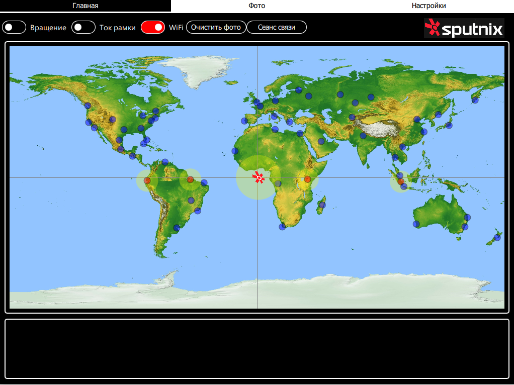
Terra Ground Control software is used to control the current frame and the globe. Figure 2 shows the main window of the program.

Picture 2. The main window of the program
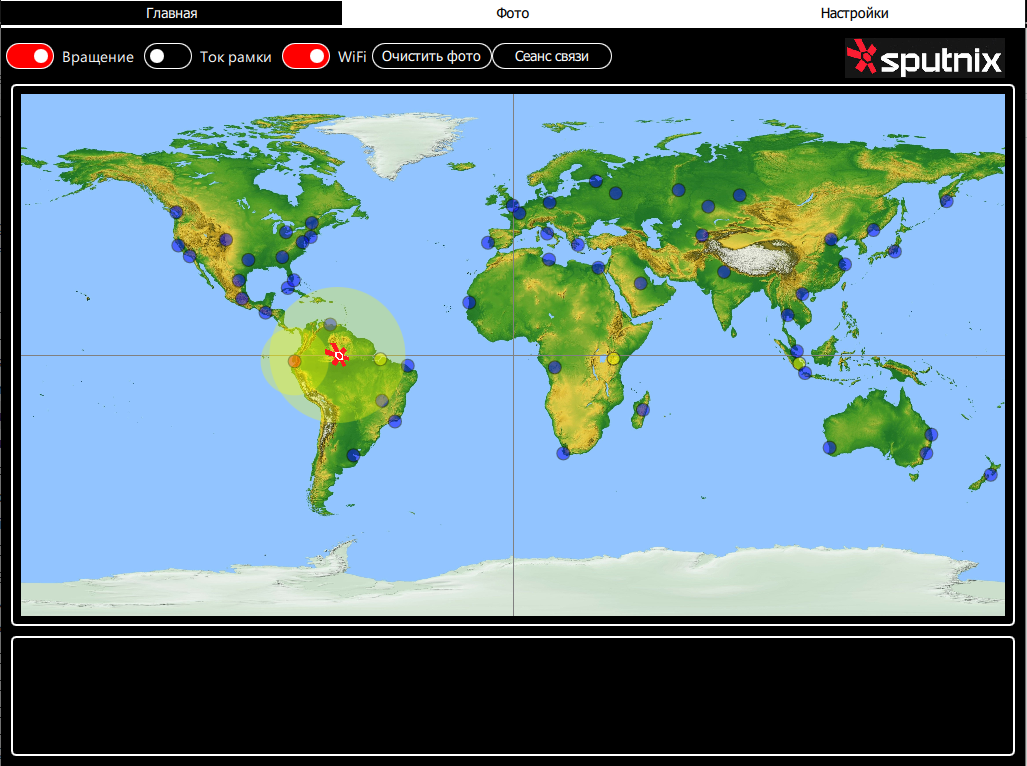
The Home tab shows a map. The cities that are highlighted on the globe are marked in blue. When Terra rotates on the sunny side of the city, the LEDs light up on the dark side, and the satellite image moves along the equator. There are also four RF receivers on the equator of the globe (yellow circles on the map) for communication with OrbiCraft 1.0 and OrbiCraft 3D, simulating receiving stations. To activate them, click on the circles in the program and they will change color to red (Picture 3):
Picture 3. Activation of reception stations on the globe (RF receivers)
The following settings are available on the Settings tab (Picture 4):
Rotation speed - adjusts the speed at which the globe rotates.
Zero setting - setting the location of the solar radiation simulator relative to the globe.
Frame current - regulates the current in a frame with an alternating magnetic field.
Telemetry interval - sets the time interval for receiving images from the satellite designer.
Connection - When connected to the Terra 2.0 wireless network, connection information will appear.
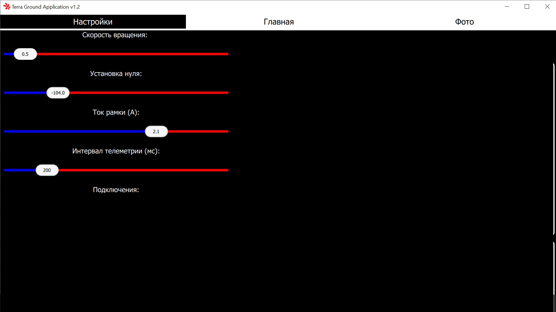
Picture 4. Settings tab in the program
Zero setting
To set zero, follow these steps:
- Start the rotation of the globe and stop at the moment when the satellite image appears at the zero point of the meridian.

Picture 5. The zero point of the meridian
Look at which meridian your satellite constructor is located above.
Go to the Settings tab and enter a value in the Zero Setting menu. If the point in front of which the satellite is suspended is west of the prime meridian, then the value is set to negative. If it is to the east, it is positive.

Picture 6. Example of setting zero

Picture 7. Updated satellite position
Connecting OrbiCraft 3D to the Terra 2.0 network
Download and unzip the file from the software Terra Ground Control sx-terra-ground_v1.8
Connect to the ORBICRAFT 3D network and open the Houston Server and Houston Application programs. Connect to OrbiCraft 3D via VHF;
Open the address F(Paspberry_Pi) and in the command execute_script enter: id=100, arg=0 in order to change the satellite constructor from the access point to the client;
If you failed to change the status of the constructor from the access point to the client, use: id=100, arg=1.
Connect to the Wi-Fi network Terra 2.0, before that, first close the Houston CC software;
Enter the router's IP address in the browser's address bar 192.168.0.1;
Open the Settings tab and wait for the designer to appear on the network;
To connect to the Web interface of the designer, enter the IP address of OrbiCraft 3D, which is specified in the Settings tab.
Transfer photos from OrbiCraft 3D to the Terra 2.0 receiving station
Orient and stabilize OrbiCraft 3D so that its camera is pointed at the area to be filmed;
Take a photo of the specified area (as indicated in 01 Lesson. Software installation and the first program), pay attention to the number of the received photo;

Picture 8. The number of the received photo
- In the Terra Ground Control software, select and activate one of the receiving stations by clicking the left mouse button.
Picture 9. Reception stations
Reception stations are located in the following cities located near the equator line:
- Belen
- Guayaquil
- Nairobi
- Palembang
- Wait for the moment when Orbicraft 3D enters the "field of view" of the selected receiving station. For convenience, you can stop the rotation at this moment;
Picture 10. Satellite entry into the "visibility zone" of the station
- Make sure that the on-board RF sensor and the RF sensor of the globe are opposite each other (the distance between them should be less than 10 cm). Run the program for transferring photos (thumbnails) in the web interface. As soon as the transfer starts, you will see that the Terra Ground Control software has the "Communication Session" icon lights up red, and the reception sensor on Terra itself lights up red.

Picture 11. Example of the program code(C++) for transferring photos No. 16
- For working in C++:
- To work in Python:
push_thumbs_terra2(uint8_t numFrom);Starts the transfer of all thumbs from Orbicraft 3D to TerraGround.
[in] numFrom - the thumb number from which the transfer begins
push_photo_terra2(uint8_t photoNum);Starts transferring photos from Orbicraft 3D to TerraGround.
[in] photoNum - photo number
pushThumbsToTerra2(self, num: int)Starts the transfer of all thumbs from Orbicraft 3D to TerraGround.
num : int - the thumb number from which the transfer begins
pushPhotoToTerra2(self, num: int)Starts transferring photos from OrbiCraft 3D to Terra Ground Control.
num : int - photo number
Picture 12. Communication session
You can transfer full-fledged photos (photos) or compressed thumbnails (thumbs). You can find the necessary functions in the custom C++ API and in the custom Python API.
- All transferred photos can be viewed in the "Photos" tab.

Picture 13. The received photos