assembling_constructor
#03 Lesson. Building the constructor
Cable network assembly
The on-board cable network is necessary for information exchange between the subsystems and the central computer, as well as for supplying power to the subsystems.
Satellite subsystems have two redundant connectors for connecting to the on-board network. Thus, the device connected to the on-board network is not only available for information exchange with it, but also provides the opportunity to connect through itself with a "garland" of subsequent subsystems in the circuit.
The information network is built on a bus architecture using RS-485 serial interfaces. To facilitate installation, the power lines and the information network are combined into one loop. The subsystems are connected via the DB-9F connector ("mom") from the harness side and DB-9M ("dad") from the device side. Since different layout of the designer elements is possible, the determination of the length of each loop, its configuration, and ultimately the manufacture remains with the user.
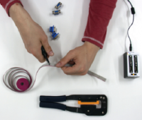
Preparation
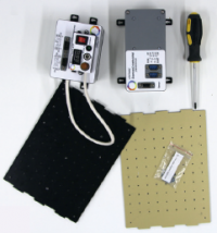
- From the OrbiCraft kit, take: a crimper, wire cutters, a loop coil, 2 "mom" connectors, a loop tester and a 12V power adapter.
- Cut the cable of the required length from the coil of the nine-channel cable included in the set with wire cutters.
Assembly of the loop
Insert the yellow insert included in the kit into the crimper.
Place the connector in the yellow insert under the center of the crimper clamping bar.
Holding the crimper with the connector with one hand, place the end of the cable into the connector with the other hand.
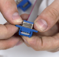
Use the crimper to clamp the connector with the inserted end of the cable until a characteristic click sounds.
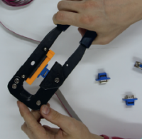
Make sure visually that the connector is locked.
Make sure that the cable is completely in the connector, but does not stick out too much on the back side.
Before making an effort to snap, press the latch slightly, make sure that the cable cores fall evenly between the contacts and only then finally snap the connector.
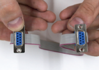
- Repeat the algorithm of actions for the second end of the cable with the second connector "mom".
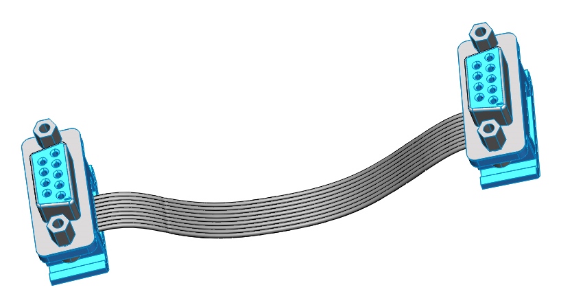
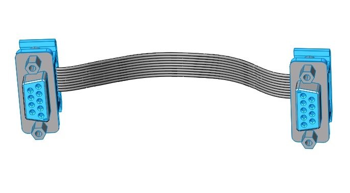
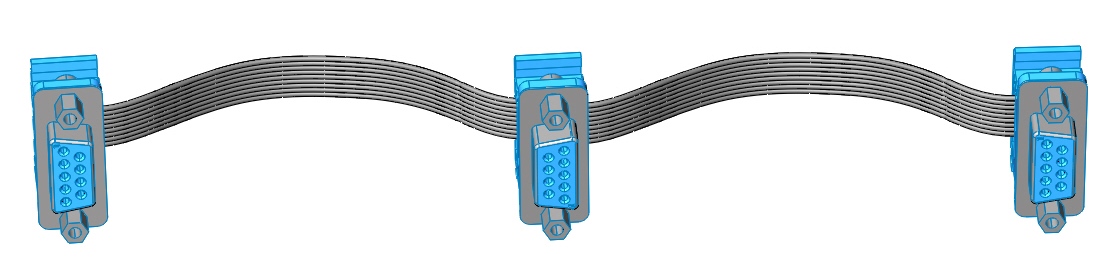
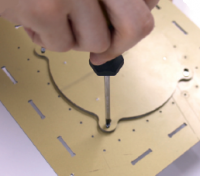
When crimping the cable, it is important to remember that the installation directions of the connectors coincide, as shown in the illustrations below.
Correct assembly:
Incorrect assembly:
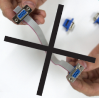
It is necessary to ensure that there is no displacement of the cable relative to the pins in the connector, as shown in the photo.
The existing pinout of the connector (the purpose of each of the contacts) minimizes the likelihood of damage to the equipment if the cable is improperly manufactured by the user. However, it does not guarantee that the device cannot be disabled in principle. It should also be noted that the manufacture and refinement of loops by the user does not require special skills and tools.
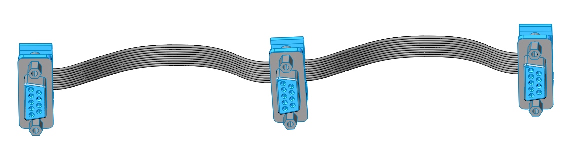
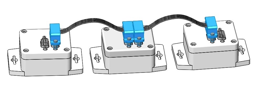
It is possible to connect all network devices in series using point-to-point cables (as in the figure below), and to create branches when using cables with more than two connectors.
The cable for connecting the camera "papa-papa" should not be longer than 40 cm.
It is forbidden to connect devices that are not intended for use "on board" (a "ground" HF receiver and a "ground" UHF telemetry receiver) and on-board network devices to the same cable network. It is especially important to ensure that the USB-RS485 ground segment connection cable and the on-board power supply system (PSS) do not end up in the same cable network. Otherwise, the components of the constructor may be damaged!
Checking the loop
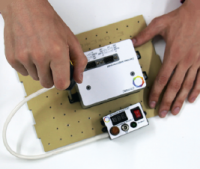
A special device is used to check the loops — a loop tester. Before starting work, the loop tester must be connected to a 220V network using an adapter.
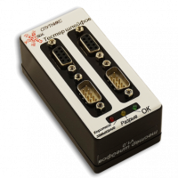
Plug the assembled cable into the appropriate connectors on the cable tester. The green light "OK" should light up.
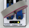
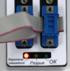
If you still have the yellow light "Break" on, then you have a circuit break. Most likely, you have not fully compressed the cable.
If you have a red light "Short circuit", it means either you damaged the insulation of two adjacent channels when crimping the loop, or incorrectly placed the two connectors relative to each other. Try to re-compress the cable by following the instructions above.
Building the constructor
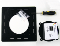
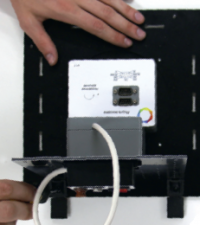
Prepare the parts for installing the flywheel motor: the base of the constructor, the flywheel module, a set of screws.
Attach the motor to the bottom plate (base) of the satellite. Attach the motor to the base with screws.
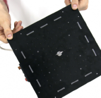
Take the four side plates — the walls of the satellite, the PSS module and the BCU, as well as a set of mounting screws. Attach the PSS module to the side plate from the inside.
Attach the plastic corners to the side plate using screws. Insert the side plate into the slots of the base plate and connect with screws and plastic corners.
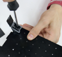
Mount the PSS remote control unit outside. Install the BKU** on another plate and attach the remaining plates to the base in the same way as the first plate. Connect the devices using cables.
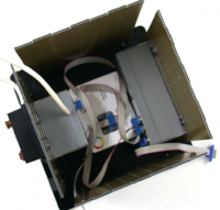
Install the upper cover of the housing and connect it with plastic corners to the side plates. Secure all corners with screws. Mount the necessary subsystems with screws and connect them using cables with BKU and PSS.
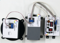
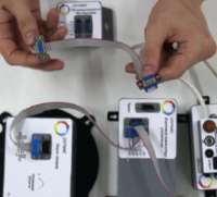
![Connecting the remaining subsystems]
Connect the modules in the following order:
- PSS → BCU → Flywheel;
- Camera → BKU;
- PSS → HF transmitter.
The remaining modules are connected sequentially in any order.
The assembly is finished!
Tasks
Complete the tasks based on the projects from the last lesson.
1) The "Alarm System" project. Change the program of the angular velocity sensor so that it responds to a slight vibration and reports that someone has touched the Orbicraft.
2) The Compass project. Change the magnetometer program so that it tells you which side of the world the Orbicraft is turned to with the power button.
3) The project "Where is the Sun?". Change the program of the solar sensors so that the Orbicraft reports from which side the bright light falls on it.