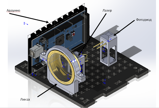
Laser communication
One of the areas being developed in modern satellite engineering is laser communication between two or more spacecraft. To simulate data transmission based on the principle of laser communication, OrbiCraft 3D educational designers assemble a separate module that allows the satellite to switch between two modes and act as both a transmitter and a receiver. To do this, the module contains the following elements:
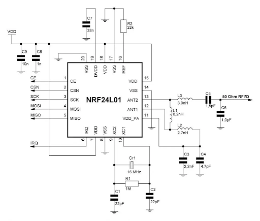
- Radio module NRF24L01 is an antenna that allows data transmission from one satellite to another;
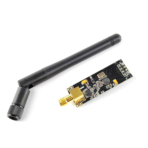
Picture 1. Radio module NRF24L01
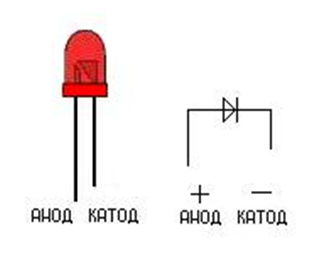
- Photodiode - which serves as a simulator for receiving data from a laser radiation source;
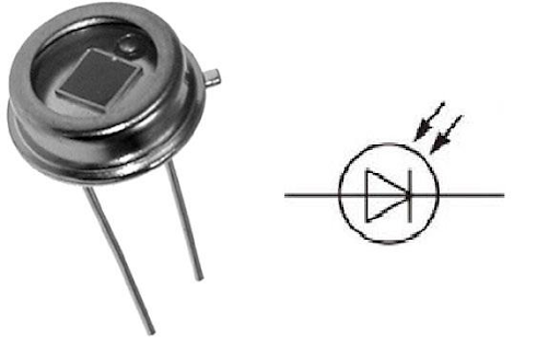
Picture 2. Photodiode
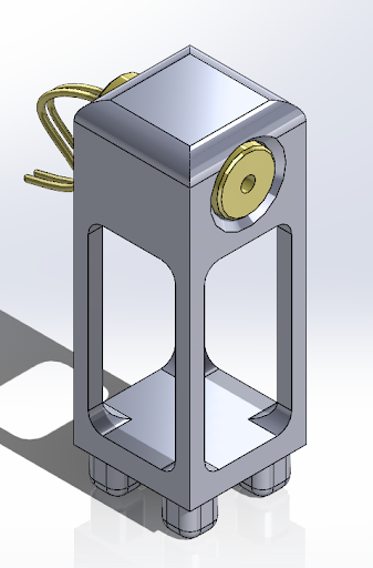
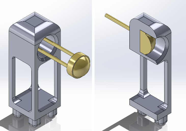
- Laser module - a laser radiation source, simulates a data transmission source over an optical channel;
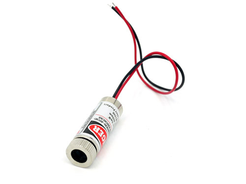
Picture 3. Laser module
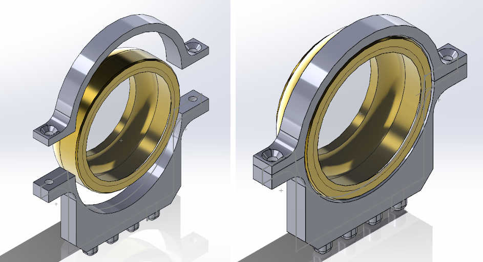
- Lens - for expanding the laser light beam;
![Lens]
Picture 4. Lens
- Laser rangefinder
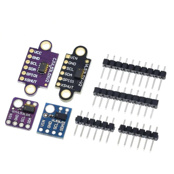
Picture 5. Laser rangefinder
Block diagram of the laser communication module for the Orbicraft 3D satellite:
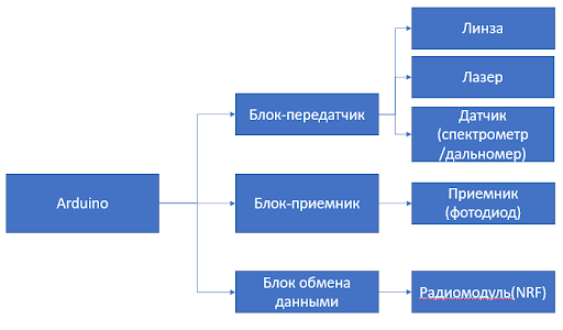
Picture 6. Block diagram of the laser communication module
The operation between the two Orbicraft 3D laser communication modules is as follows:
The two satellites must orient themselves so that the laser beam can hit the photodiode (receiver). In the conditions of a real space flight, data transmission would begin at this moment via the optical channel. But the laser radiation source requires high power, so data transmission via a conventional laser module is impossible. Returning to the educational experiment. After the photodiode detects the laser source and realizes that this mutual orientation of the satellites is stable, data transmission begins between the NRF24L01 radio modules: the transmitter sends data to the receiver, the receiver receives the data, processes it and sends it to the Houston App.
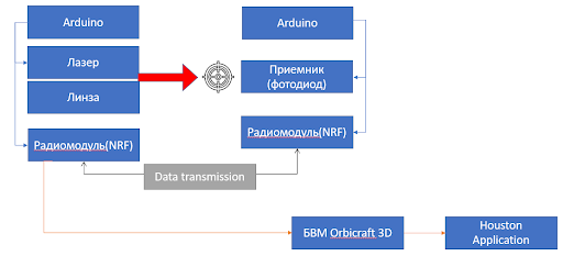
Picture 7. Scheme of operation between two laser communication modules
Instructions for assembling a laser communication system for two Orbicraft 3D satellites.
1.Assembly of the universal laser communication module
Rule
1.1. Assembly and installation of the lens stand
To install the lens on the payload module, you will need an upper rim and a lower lens stand. Unscrew the half of the lens and place the half with a large diameter on the bottom rack. Cover the top with a rim and tighten with screws on the sides.
Picture 8. Assembly and installation of the lens stand
2.Installation of the laser module and photodiode in racks
Rule
2.1. Installation of the laser module
The laser is installed by simply inserting the module into the hole in the rack.
Picture 9. Installation of the laser module
2.2. Installing the photodiode
Just like a laser, a photodiode is installed in a rack by concentrating the diameters of the photodiode and the hole of the rack. Push the photodiode through to the end so that its legs enter the small holes for this, and the photodiode body itself is completely recessed into the hole of the rack.
Picture 10. Installing a photodiode
3.Placement of elements in the payload module
After you have assembled the individual structural elements, install them on the base of the payload module. The main criterion that must be observed during assembly is the alignment of the photodiode, laser and lens. That is, these parts must be on the same horizontal to ensure the accuracy of the experiment.
Picture 11. Placement of elements in the payload module
Connecting modules to the Arduino board
Before fully turning on the laser communication module, it is recommended to first master the connection of the photodiode, NRF radio module, etc. step by step. The separately elaborated steps will help to better understand the operation of laser communication in the satellite designer.
1.Operation of the photodiode
The principle of operation of the photodiode is simple. It converts the light that hits it into an electric charge due to the p-n junction. Let's try to output the values from the photodiode to the port monitor. To do this, connect the plus photodiode to any analog input, do not forget about the GND pin.
Picture 12. Photodiode
You will need commands:
``cpp commands.c int potValue[1];//initialize the data array potValue[0] = analogRead(A1);//read the data array from pin A1
### 2.Communication between two Arduino using NRF radio modules
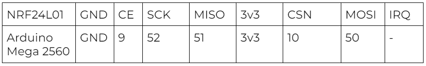
Since our laser module is not designed to transmit data through a laser beam, as in real space systems, it becomes necessary to somehow simulate data transmission. The NRF radio module will be used for this purpose. This is the key essence of the educational module of laser communication - data is transmitted not through a laser, but via radio communication. Check out the electrical diagram of the NRF module for correct connection of pins:
_Picture 13. Electrical diagram of the NRF module_
You will also need the [ARDUINO MEGA 2560 DATA PINOUT] circuit(/files/orbicraft3d/arduino_mega2560_pinout.pdf)
The NRF24L01 radio module is connected to the Arduino via the SPI interface, which involves the use of 5 wires, not counting the power terminals. The CE and CSN pins can be connected to any Arduino digital pins. The only thing that is required is to specify their numbers when writing the sketch. As for programming, there are several libraries for interacting with NRF24L01, but the most popular and stable is the RF24 library.
_Picture 14. RF24 Library_
Below are the commands for the receiver and transmitter that you will need when working with the radio module:
**Sample sketch for the transmitter**
```cpp transmitter.c
#include <SPI.h> // Connecting the library to work with the SPI interface
#include <nRF24L01.h> // Connecting the configuration file from the RF24 library
#include <RF24.h> // Connecting the library to work with the NRF24L01 module
#define PIN_CE 9 // The pin number of the Arduino to which the CE pin of the radio module is connected
#define PIN_CSN 53 // The pin number of the Arduino to which the CSN pin of the radio module is connected
RF24 radio(PIN_CE, PIN_CSN); // Creating a radio object with the CE and CSN
void setup() pins {
radio.begin(); // Initializing the NRF24L01 module
radio.setChannel(5); // Data exchange will be conducted on the fifth channel (2.405 GHz)
radio.setDataRate (RF24_1MBPS); // Data exchange rate of 1 Mbit/sec
radio.setPALevel(RF24_PA_HIGH); // Select the high power of the transmitter (-6dBm)
radio.openWritingPipe(0x778787878ll); // Open the pipe with a unique ID
}
void loop() {
///////////////////////////////////////////// Here you can read the data from the photodiode
radio.write(potValue, 1); // Sending the read readings over the radio
channel }
``
**Sample sketch for the receiver**
```cpp receiver.c
#include <SPI.h> // Connecting the library to work with the SPI interface
#include <nRF24L01.h> // Connecting the configuration file from the RF24 library
#include <RF24.h> // Connecting the library to work with the NRF24L01 module
#define PIN_CE 9 // The pin number of the Arduino to which the CE pin of the radio module is connected
#define PIN_CSN 53 // The pin number of the Arduino to which the CSN pin of the radio module is connected
RF24 radio(PIN_CE, PIN_CSN); // Creating a radio object with the CE and CSN
void setup() pins {
radio.begin(); // Initializing the NRF24L01 module
radio.setChannel(5); // Data exchange will be conducted on the fifth channel (2.405 GHz)
radio.setDataRate (RF24_1MBPS); // Data exchange rate of 1 Mbit/sec
radio.setPALevel(RF24_PA_HIGH); // Select high transmitter power (-6dBm)
radio.openReadingPipe (1, 0x778787878ll); // Open the transmitter ID pipe
radio.startListening(); // Starting to listen to the pipe being opened
void loop() {
if(radio.available()){ // If data has been received in the receiver buffer
radio.read(&distance, sizeof(distance));
Serial.print("Recevied: ");
Serial.println(distance);
delay(200);
}
}
3.Connecting the rangefinder
Any telemetry can be transmitted over the radio link between the two NRFs. As part of the study of the designer, we will try to transfer data from a rangefinder that is connected to one of the microcontrollers. To connect the rangefinder, use the connection diagram below:

Picture 15. Connection diagram of the rangefinder
You will need the library Adafruit_VL53L1X.h
Example of a sketch for a rangefinder:
lidar.c
#include "Adafruit_VL53L1X.h"


#define IRQ_PIN 2
#define XSHUT_PIN 3


Adafruit_VL53L1X vl53 = Adafruit_VL53L1X(XSHUT_PIN, IRQ_PIN);


void setup() {
  Serial.begin(115200);
  while (!Serial) delay(10);


  Serial.println(F("Adafruit VL53L1X sensor demo"));


  Wire.begin();
  if (! vl53.begin(0x29, &Wire)) {
    Serial.print(F("Error on init of VL sensor: "));
    Serial.println(vl53.vl_status);
    while (1)       delay(10);
  }
  Serial.println(F("VL53L1X sensor OK!"));


  Serial.print(F("Sensor ID: 0x"));
  Serial.println(vl53.sensorID(), HEX);


  if (! vl53.startRanging()) {
    Serial.print(F("Couldn't start ranging: "));
    Serial.println(vl53.vl_status);
    while (1)       delay(10);
  }
  Serial.println(F("Ranging started"));


  // Valid timing budgets: 15, 20, 33, 50, 100, 200 and 500ms!
  vl53.setTimingBudget(50);
  Serial.print(F("Timing budget (ms): "));
  Serial.println(vl53.getTimingBudget());


  vl.VL53L1X_SetDistanceThreshold(100, 300, 3, 1);
  vl.VL53L1X_SetInterruptPolarity(0);
  */
}


void loop() {
  uint16_t distance;


  if (vl53.dataReady()) {
    // new measurement for the taking!
    distance = vl53.distance();
    if (distance == -1) {
      // something went wrong!
      Serial.print(F("Couldn't get distance: "));
      Serial.println(vl53.vl_status);
      return;
    }
    Serial.print(F("Distance: "));
    Serial.print(distance);
    Serial.println(" mm");


    // data is read out, time for another reading!
    vl53.clearInterrupt();
  }
}
Connecting the laser communication module to OrbiCraft 3D
The tasks completed above will help you implement a laser communication system between two satellites. This is the final stage of preparing and assembling the laser communication module for operation. In the next stages, you will need to configure OrbiCraft 3D itself to work with it.
Recall that the final purpose of the transfer is to send data from any sensor, for example, a rangefinder, to one satellite, and then, through it, output it to the Houston Application. To send data to the Houston Application, it is necessary that the data received from the Arduino is first transmitted via the CAN bus to the BVM. To do this, use the library <unican_ard.h> and some commands:
``cpp commands.c UCanArd.Init(); UCanArd.SendMessage(0xF, 0x0118, (uint8_t*)&distance, sizeof(uint16_t));
After embedding these commands in the Arduino code for the receiver, you can be sure that the data received from the rangefinder will be transmitted to the Orbicraft BVM.
Since the Arduino cannot be directly connected to the satellite's BVM, an adapter is needed, thanks to which Orbicraft would understand that something is connected to it via Arduino. To do this, the Arduino Shield is used - a transitional device that repeats the original Arduino channels and allows you to connect to the satellite via the CAN bus.
At this stage, you need to connect all modules to the Arduino through this special Shield.
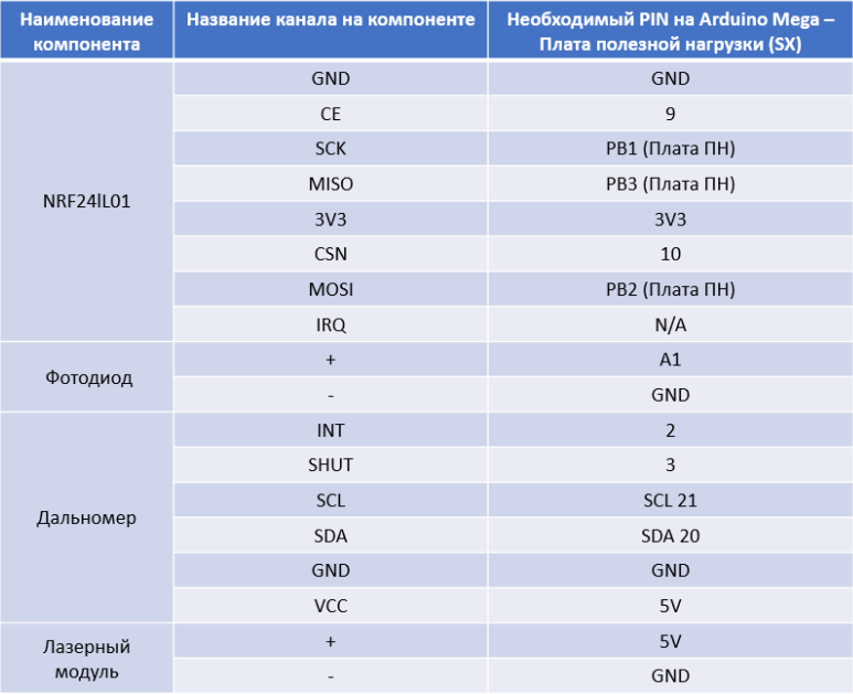
_Picture 16. Connecting the laser communication module_
## Working with the Houston Application
Let's fix the essence of the laser communication module between two educational designers. Firstly, on the Orbicraft, which is a transmitter, there is a photodiode and a rangefinder. When the rangefinder values are rejected due to the laser beam passing through the lens and eventually hitting the photodiode, data begins to be transmitted from the transmitter via NRF to the receiver on which the lens and laser are installed.
The receiver, having received data from the rangefinder, processes them and transmits them via the CAN bus to the satellite's BVM. Then, via WI-Fi, the satellite receiver sends data to the Houston Application.
In order to display the values that are sent to the receiver satellite, it is necessary:
1) Correctly configure the IP address of the satellite you are working with. To do this, go to the File tab, then Parameters, then Connections. In the serverAddress line, make sure that you have the correct IP address of the satellite from which you are receiving data.
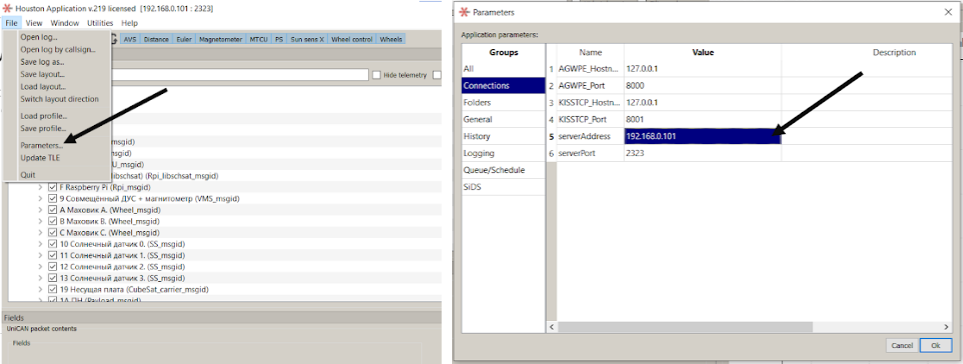
_Picture 17. Setting up an IP address_
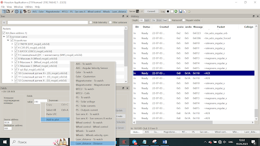
2) If everything is connected correctly, leave a check mark in the Packets window only for 1A MON. After that, in the History column, you will have the data that the rangefinder transmits. Click on any value on the right and in the Fields window, then Value you will see the distance that the rangefinder sent in millimeters.
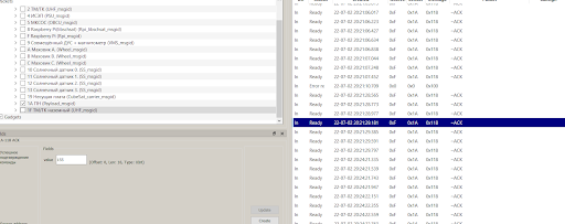
_Picture 18. Data sent by the rangefinder_
3) To visualize the data, go to the Window, then New Instrument Panel and name the graph, for example, Distance. Next, Add, Custom Plot and without changing anything, click OK. Now the received data is reflected in the form of a graph
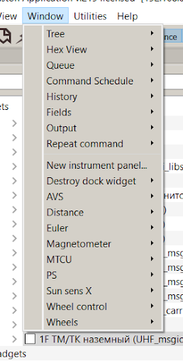
_Picture 19. Adding a new panel_
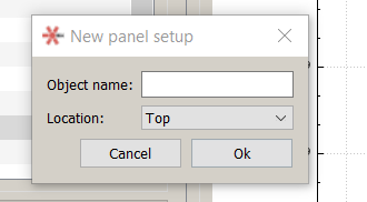
_Picture 20. New Panel Settings_
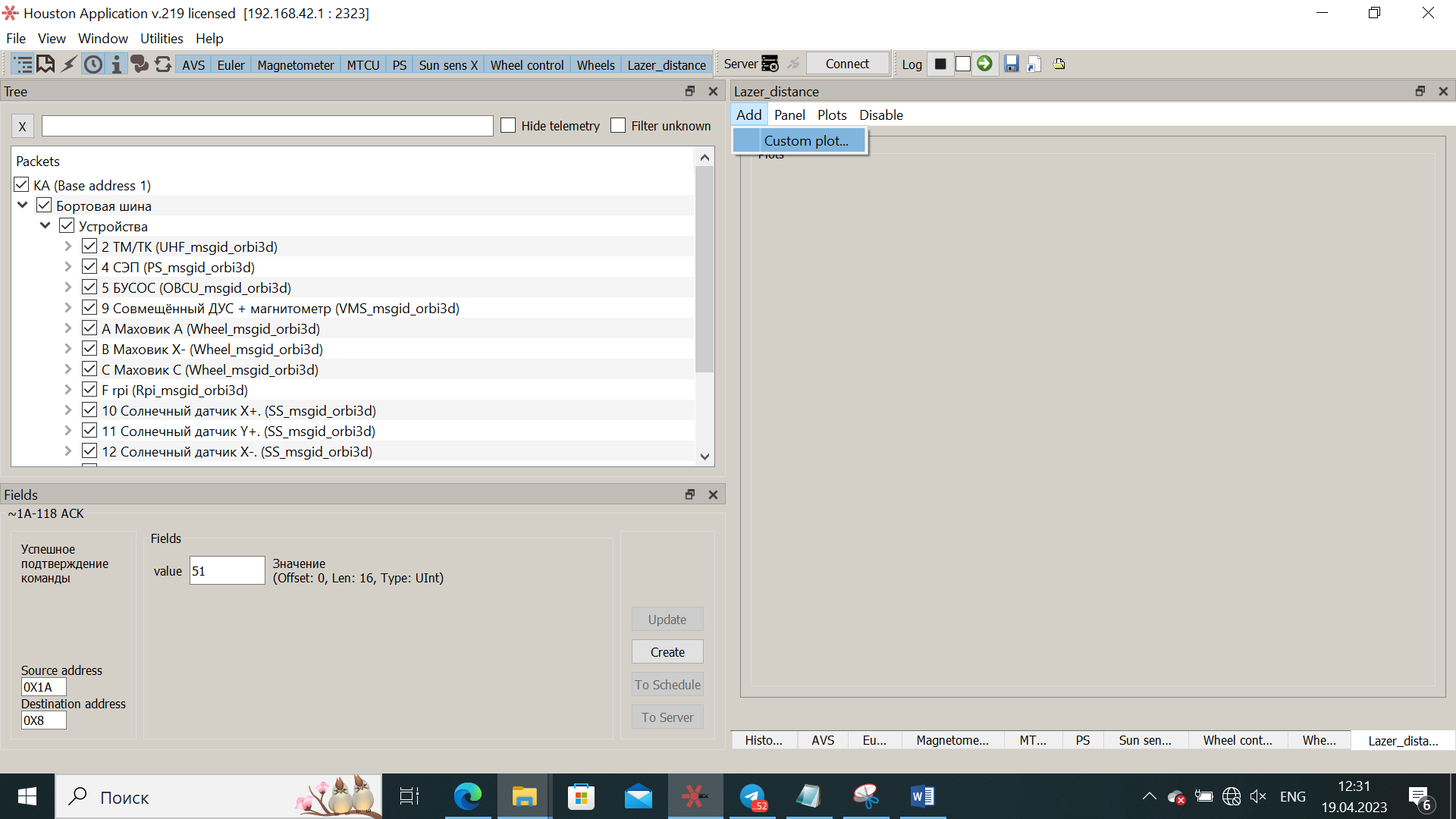
_Picture 21. Adding a new schedule_
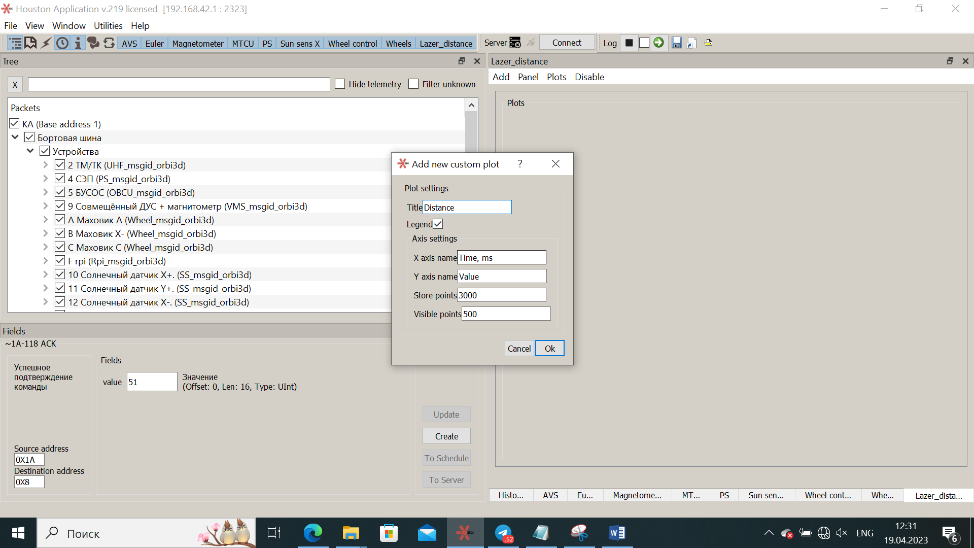
_Picture 22. New Schedule Settings_
_Picture 23. Displaying the created graph_
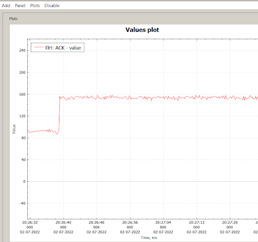
_Picture 24. The resulting graph_
## Schemes of the experiment
Several experimental schemes are proposed to study the operation of laser communication module devices. In fact, they are all the same: the satellites must orient themselves so that one of them can get into the photodiode of the second satellite with a laser. After that, the data transfer will begin. The proposed experimental options differ only in the position of external factors: the position of the sun or the direction of the magnetic field.
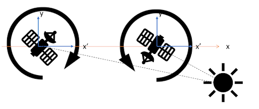
### Scheme of experiment No. 1:
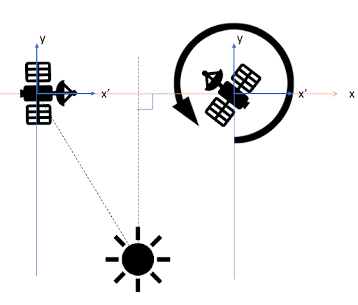
_Picture 25. Scheme of experiment No. 1_
In this experimental scheme, the centers of mass of the devices are located on the same horizontal axis. The light source simulating the sun is located on the axis of symmetry between the two satellites at some distance from the main horizontal. In this case, the luminous flux from the source approaches the solar sensors on the devices at the same angle α. Let's assume that one of the satellites is already oriented in the right way and is at an angle α with respect to the sun, while the second one is trying to orient itself in the right way. After the second satellite turns to the required roll angle and hits the receiver's photodiode with a laser, data transmission begins.
### Scheme of experiment No. 2:
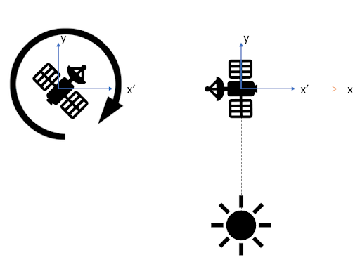
_Picture 26. Scheme of experiment No. 2_
In the second version of the experiment, the following difference from the previous one: one of the satellites at the initial stage is also already oriented, but not at an angle α, but at an angle of 0 ° / 180 °. Next, the second satellite, as in the first variant, needs to turn to a certain angle in order to get its laser into the photodiode of the receiver.
### Scheme of experiment No. 3:
_Picture 27. Scheme of experiment No. 3_
The third version of the experiment differs fundamentally from the previous two in that both satellites are not oriented in any way at the very beginning, that is, they are in free rotation. At the same time, the sun is behind one of the satellites. Therefore, each satellite needs to choose its own rotation angle in order to point the laser communication modules at each other.
## Implementation of the orientation system via the Web interface
The above options for implementing the experiment are based on the fact that a certain angle must be reached between the X-axis of the device and the sun. You must first calculate the angle yourself, based on how far the sun is and at what distance the Orbicrafts are located between each other. In the first two experimental schemes, the satellite on which the photodiode is located should already be in a stable state with respect to the sun. Therefore, calculate the angle manually using simple geometric ratios.
You turn on one satellite first and select an angle for it.
You turn on the second satellite (which shines with a laser), select for it the angle that should be between it and the sun.
After it stabilizes from an uncertain state and hits the photodiode of the second satellite with its laser, data transmission to the satellite with the laser and then from it to Houston will begin.
In order to orient your satellites in the right way, you will need to specify the relationship between the solar sensor and the flywheel in the program code.
:::tip
It is known that the X-axis of the device passes through the solar sensor “Sensor 4". You need to remember where your photodiode and laser are pointing. The case when the laser shines co-directionally with the X vector of the device and shines in the reverse direction is very similar. But the angle set in the program will be different, since the angle is calculated by the shortest turn from the vector X to the direction of sunlight.
:::
The key point of the program will be that your flywheel maintains a certain rotation speed to keep it in a certain position, stabilizing it and constantly orienting the satellite at a given angle between the solar sensor and sunlight.