Assembly of the payload housing with the installation of sensors
The body of the additional payload module is assembled in the same way as all other modules. The sensors are installed in the housing in any convenient way to complete the task. Below is an example of one of the assembly options.
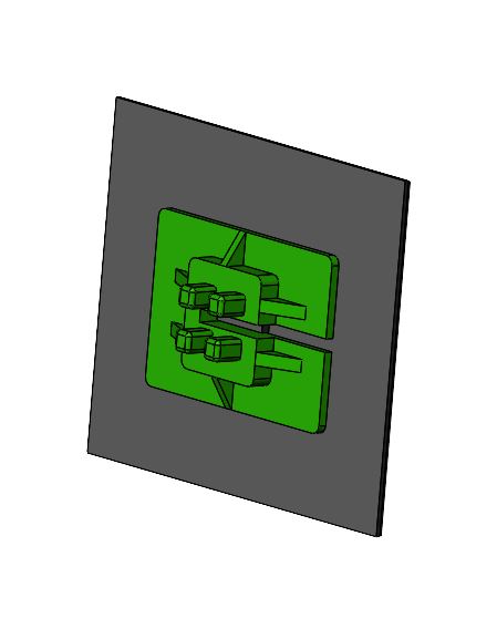
Components required to build the module (Picture 1):
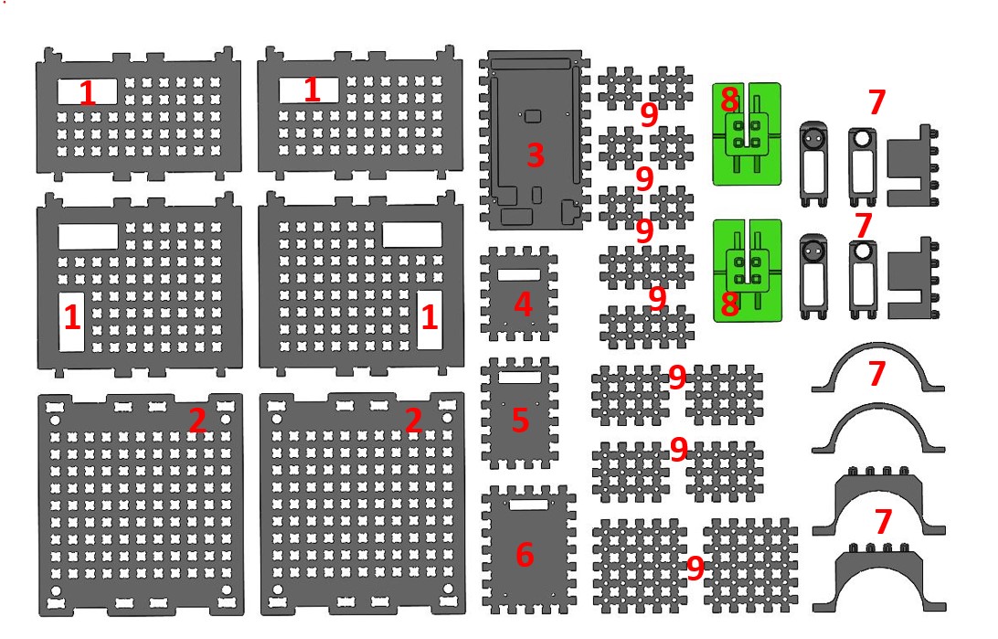
Picture 1. Housing Assembly Components
1 - Side walls;
2 - Upper and lower bases;
3 - Base for Arduino Mega;
4 - The body of the spectrum analyzer;
5 - The body of the laser rangefinder;
6 - LCD display housing;
7 - Details for lens and photodiode (laser connection);
8 - Solar panel bases;
9 - Additional fasteners.
Connect the side walls to the bases (Picture 2):
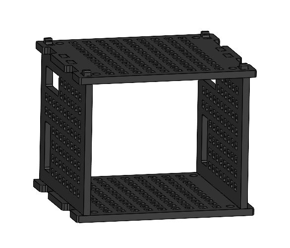
Picture 2. Housing assembly
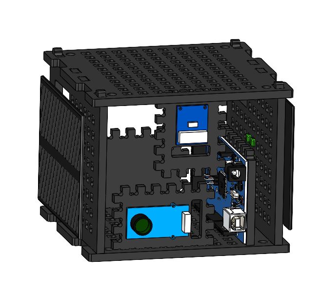
Attach the Arduino Mega board to its base (point 3 of Fig.1) and install it inside the housing on the side wall (Picture 3):
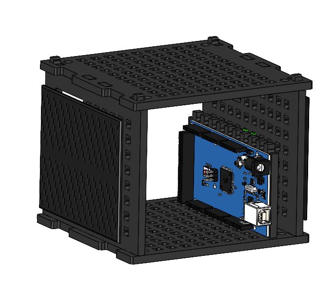
Picture 3. Installing the Arduino board into the case
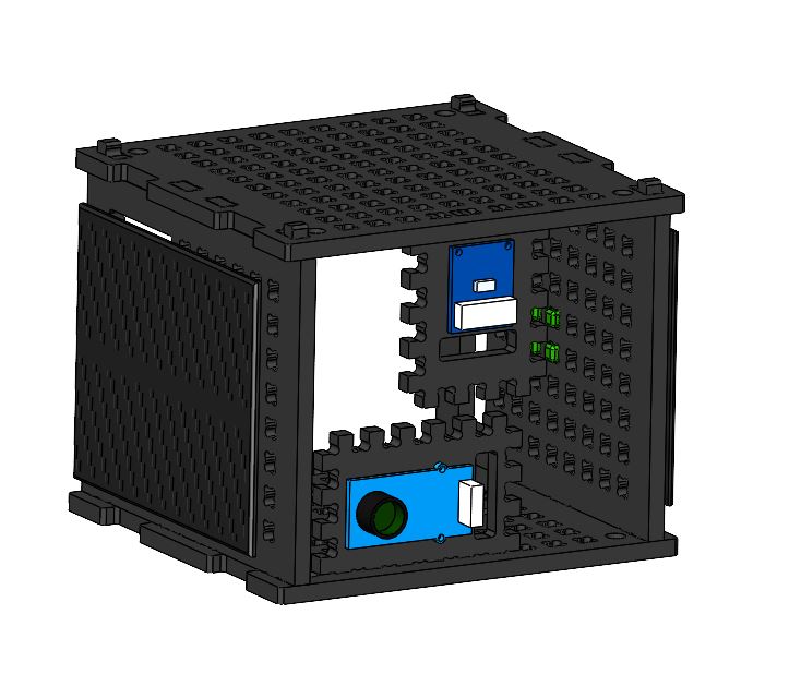
Connect the laser rangefinder to its body (point 5 in Fig.1) and install inside the module as shown in Figure 4:
Picture 4. Installation of a laser rangefinder
Connect the spectrum analyzer to its housing (point 4 in Fig.1) and install inside the module as shown in Figure 5:
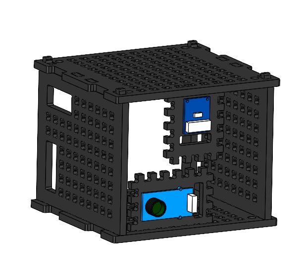
Picture 5. Installing a spectrum analyzer
Attach the two bases (point 8 in Fig.1) to the solar panel (Picture 6):
Picture 6. Installing the bases on the solar panel
Attach the assembled structure to the side wall of the payload module (Picture 7):
Picture 7. Installing a solar panel on the payload housing
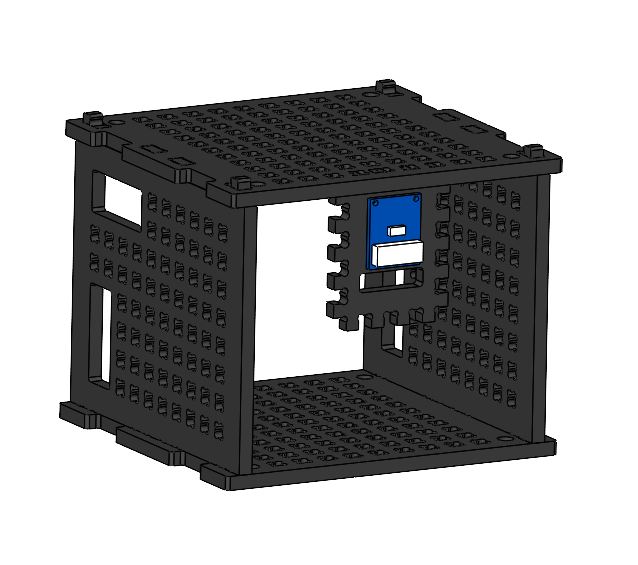
Connect the LCD display to its base (point 5 of Fig. 1) and install in the payload housing (Picture 8):
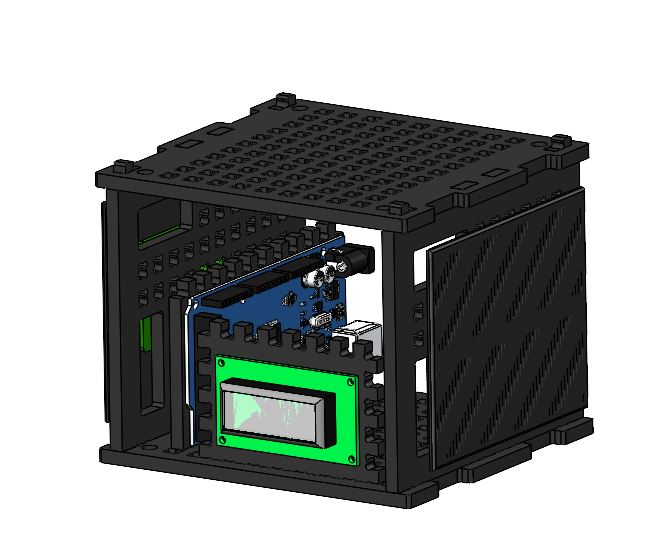
Picture 8. Installing the LCD display in the payload housing
The assembled module looks like this (Picture 9):
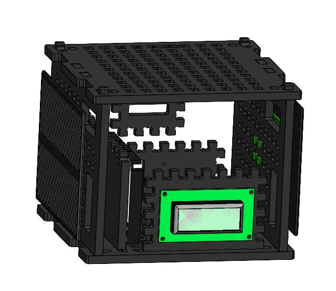
Picture 9. Complete assembly
For information on how to build and work with the laser communication module, see the article Laser Communication.