02 Lesson. Getting to know the sensors
The angular velocity sensor and magnetometer are installed in the BVM module of the OrbiCraft 3D designer (Picture 1):
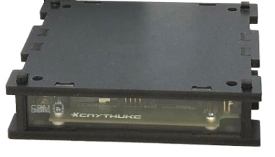
Picture 1. BVM module with AVS and magnetometer
Angular velocity sensor
Purpose of the angular velocity sensor
The angular velocity sensor is designed to measure the angular velocity of a rotating object. It is necessary to measure the angular velocity in order to stop the rotation of the satellite and stabilize it. Also, using the angular velocity sensor, you can make the satellite rotate at a certain speed.
The principle of operation of the angular velocity sensor
The main measuring element of the angular velocity sensor is a special microelectromechanical (MEMS) gyroscope. This is not an ordinary gyroscope, in which a disk rotates at high speed, but a miniature vibrating gyroscope. There is a ring inside the MEMS gyroscope that oscillates in the same plane (Picture 2). If such a gyroscope is placed on a rotating platform, the plane of which coincides with the plane of oscillation of the ring, then the Coriolis force proportional to the speed of rotation of the platform will begin to act on it. The Coriolis force is measured using piezoelectric elements that produce a voltage proportional to the applied force:
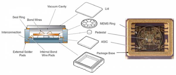
Picture 2. AVS construction
By determining the Coriolis force and knowing the rate of oscillation, you can calculate the angular velocity and its change (angular acceleration).
![Sensor chip]
Picture 3. Sensor element chip
Checking the operability of the angular velocity sensor
Connect the BVM to the BOT. Open the Web interface and write the following program.
#include <stdio.h>
#include <stdint.h>
#include "libschsat.h"

void control(void){

    float gyro_x = 0, gyro_y = 0, gyro_z = 0;
    uint16_t gyro_num = 0;
    gyro_set_offset(0, 0, 0, 0);

    for (int i = 0; i < 20; i++){
        mSleep(1000);
        gyro_request_raw(gyro_num, &gyro_x, &gyro_y, &gyro_z);
        printf("Gyro: %f %f %f\n", gyro_x, gyro_y, gyro_z);
    }
    puts("Sent");
}
Run the program and test the AVS operation.
The program in the WEB interface (Picture 4):
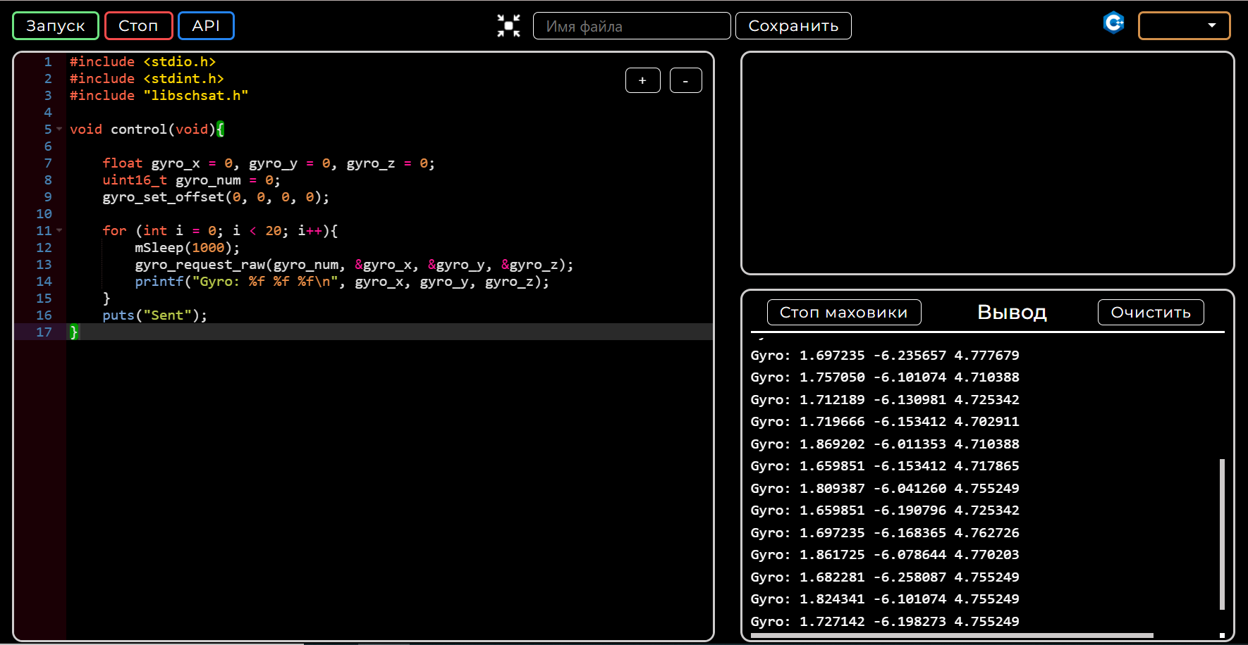
Picture 4. The program code in the Web interface and an example of the data obtained using it
Code analysis
Create the variables gyro_x, gyro_y, gyro_z to receive data from the sensor and the variable num storing the AVS number.
The mSleep(1000) function suspends program execution for 1 second.
Then in the for loop (int i = 0; i < 20; i++) we read and output the AVS value 20 times.
The AVS readings are read using the function:
gyro_request_raw(gyro_num, &gyro_x, &gyro_y, &gyro_z)
Zero offset
Often, the angular velocity sensor has a zero offset, and at rest shows non-zero values.
In order to increase the accuracy of the sensor readings, a special function is used to set the zero offset
gyro_set_offset (uint16_t num, float offset_X, float offset_Y, float offset_Z)
Let's learn how to use it. Set the Orbicraft stationary and run the previous AVS test program.
In the stationary state, the sensor readings will be approximately the same (Picture 5):
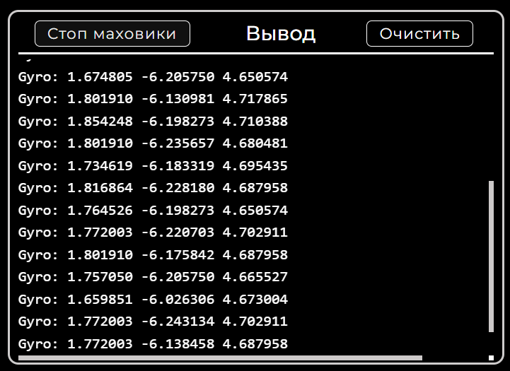
Picture 5. Sensor readings in the stationary state
To check the operation of the zero offset setting function, run the following program:
#include <stdio.h>
#include <stdint.h>
#include "libschsat.h"

void control(void){

    float gyro_x = 0, gyro_y = 0, gyro_z = 0;
    uint16_t tmp=0;

    Sleep(1);
    gyro_set_offset(tmp, gyro_x, gyro_y, gyro_z);
    Sleep(1);
    gyro_request_raw(tmp, &gyro_x, &gyro_y, &gyro_z);
    printf("Before fix:\n %f %f %f", gyro_x, gyro_y, gyro_z);
    Sleep(1);
    gyro_set_offset(tmp, gyro_x, gyro_y, gyro_z);
    Sleep(1);
    gyro_request_raw(tmp, &gyro_x, &gyro_y, &gyro_z);
    printf("\nAfter fix:\n %f %f %f \n", gyro_x, gyro_y, gyro_z);
    uint8_t data[0];
    send_unican_message(25, 2656, data, 0);
}
In this program, we initially reset the values of angular velocities, after which we overwrite the averaged values obtained after the first calculation into the same variables and, based on them, perform the calculation again.
Now the AVS readings at rest almost do not differ from zero (Picture 6):
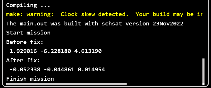
Picture 6. Comparison of AVS readings
Viewing a graph of AVS values
Launch the Houston App and connect to it via Wi-Fi as described on this page.
In this mode, on the AVS tab, you can view a graph of changes in the values returned by the angular velocity sensor (Picture 7):
Picture 7. Graph of changes in AVS values
Magnetometer
Purpose of the magnetometer
The satellite receives orientation information from an angular velocity sensor and a magnetometer. Information about the angle is needed in order to turn the satellite in the right direction, and information about the angular velocity is necessary in order to stabilize the satellite, that is, to extinguish angular rotation. The control moment is created using a flywheel motor.
The principle of operation of the magnetometer
The operation of the magnetometer is based on the application of the magnetoresistive effect, when the electrical resistance of the conductor changes in accordance with the direction of the magnetic field lines. The sensor is based on a permalloy layer (a special nickel-iron alloy), which has a strong magnetoresistive effect. The electrical resistance of permalloy usually varies in the range of ± 5% depending on the strength and direction of the active magnetic field (Picture 8):
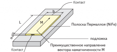
Picture 8. Magnetometer design
Thus, by measuring the strength of the current flowing through the permalloy layer when a constant voltage of + 5V is applied, the direction of the magnetic field lines can be determined. In order to measure the direction of the magnetic lines along all three axes, three small sensors oriented along the X, Y and Z axes are used, installed in one chip (Picture 9):
![Direction of magnetic lines along three axes]
Picture 9. The direction of magnetic lines along three axes
Checking the performance of the magnetometer
Connect the BVM to the BOT. Open the Web Interface and write the following program:
#include <stdio.h>
#include <stdint.h>
#include "libschsat.h"

void control(void){

float mag_x = 0, mag_y = 0, mag_z = 0;
uint16_t mag_num = 0;

for (int i = 0; i < 20; i++){
    mSleep(1000);
    magnetometer_request_raw(mag_num, &mag_x, &mag_y, &mag_z);
    printf("Mag: %f %f %f\t\n", mag_x, mag_y, mag_z);
}
puts("Sent");
}
The program in the WEB interface (Picture 10):
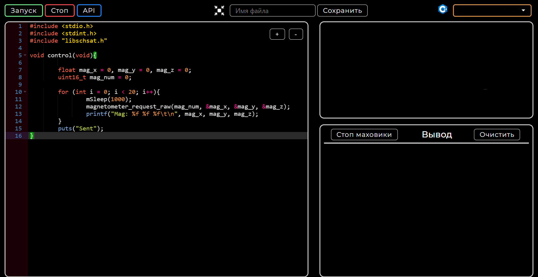
Picture 10. The program in the Web interface
Run the program and test the operation of the magnetometer.
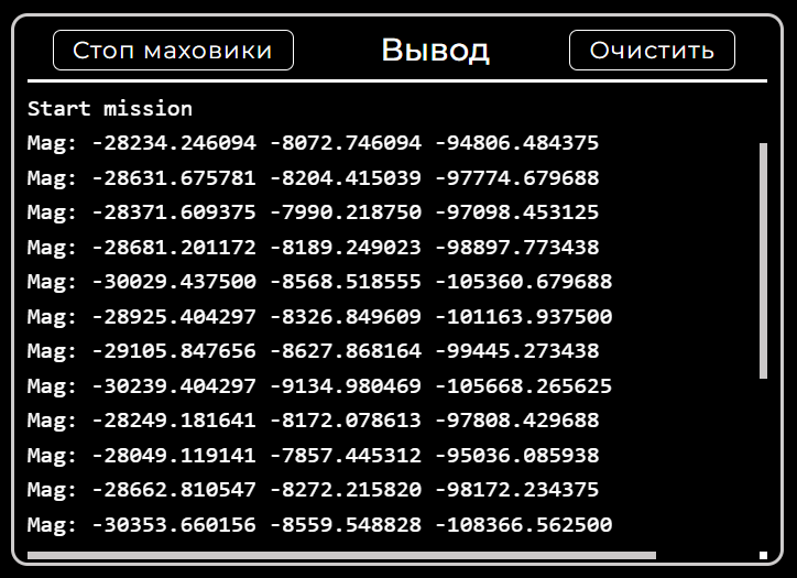
Picture 11. An example of the received data
Code analysis
We create the variables mag_x, mag_y, mag_z to receive data from the sensor and the variable num, which stores the number of the magnetometer.
The mSleep(1000) function suspends program execution for 1 second.
Then, in the for (int i = 0; i < 20; i++) loop, we read and output the magnetometer value 20 times.
The magnetometer readings are read using the function:
magnetometer_request_raw(mag_num, &mag_x, &mag_y, &mag_z)
Viewing a graph of magnetometer values
Launch the Houston App and connect to it via Wi-Fi as described on this page.
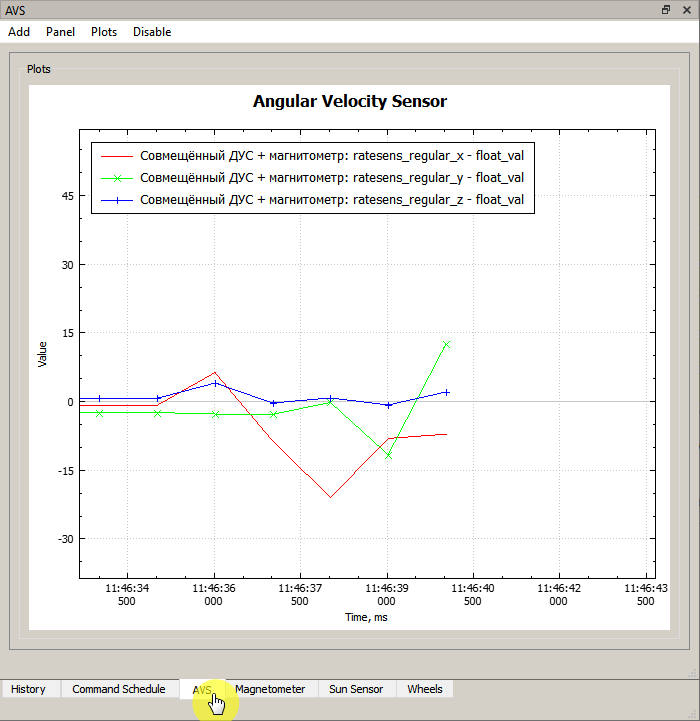
In this mode, on the Magnetometer tab, you can view a graph of changes in the values returned by the magnetometer (Picture 12):
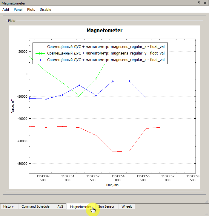
Picture 12. Graph of changes in magnetometer values
User API
The User API reference with all the functions of working with OrbiCraft 3D can be found on the pages: User API in C++ and User API in Python.