04 Lesson. Satellite stabilization
Satellite stabilization mode means maintaining zero angular velocity. Such a mode is necessary, for example, to obtain clear images or transmit them to a ground receiving point when the data transmission time is long and it is not permissible for the satellite antenna to deviate from the direction to the ground receiving point. The theory described in this lesson is also suitable for maintaining any required angular velocity, not just zero, for tasks such as tracking a moving object.
How to implement the stabilization mode
The angular velocity of the satellite can be changed using flywheels, jet engines, electromagnetic coils, gyrodyne engines. In this example, we will consider controlling the control torque using a flywheel. The operation of this device is based on the law of conservation of angular momentum. For example, when the flywheel engine spins in one direction, the spacecraft, accordingly, begins to rotate in the other direction under the action of the same torque, but directed in the opposite direction in accordance with Newton's third law. If, under the influence of external factors, the spacecraft began to turn in a certain direction, it is enough to increase the speed of rotation of the flywheel in the same direction and the undesirable rotation of the spacecraft will stop, instead of the satellite, the rotational moment will "absorb" the flywheel. We will receive information about the angular velocity of the satellite using an angular velocity sensor. In this example, we will consider how to calculate the control commands for the flywheel based on the readings of the angular velocity sensor and the data on the speed of rotation of the flywheel so that the satellite is stabilized or maintains the required angular velocity.
Theory
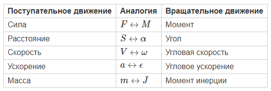
Analogies between translational and rotational motion
An analogue of the law of conservation of momentum for rotational motion is the law of conservation of angular momentum or the law of conservation of kinetic momentum:
In general, the rotational motion of a satellite is described by laws similar to those known for translational motion. So, for example, for each parameter in translational motion there is a similar parameter for rotational motion:
The laws of motion also look similar
![Laws of Motion]
Output of the ratio for the required angular velocity of the flywheel
Let's write down the law of conservation of the kinetic moment of the satellite+flywheel system for the moments of time "1" and "2":
The absolute speed of the flywheel, i.e. the speed of the flywheel in an inertial coordinate system, for example, connected to the Earth, is the sum of the angular velocity of the satellite and the angular velocity of the flywheel relative to the satellite, i.e. the relative angular velocity of the flywheel:
Please note that the flywheel can measure its own angular velocity relative to the satellite body or relative angular velocity.
Let's express the angular velocity of the flywheel, which must be set
Let's denote the relation as .
For the algorithm to work, it is not necessary to know the exact value of , because the flywheel cannot instantly set the required angular velocity. Measurement noises also interfere with the control process: the angular velocity of the satellite measured using an angular velocity sensor is not accurate, because there is always a constant error and measurement noise in the measurements. It should be noted that angular velocity measurements and the issuance of commands to the flywheel occur with a certain minimum step in time. All these limitations lead to the fact that is selected experimentally or detailed computer models are built that take into account all the above limitations. In our case, the coefficient will be selected experimentally.
Angular velocity at time "2" is the target angular velocity, let's denote it . Thus, if it is necessary that the satellite maintain the angular velocity of , then knowing the current angular velocity of the satellite and the current angular velocity of the flywheel, it is possible to calculate the desired flywheel speed to maintain the "rotation at constant speed" mode:
Using the constant speed rotation mode, you can make the satellite turn at any angle if you rotate the satellite at a constant speed for a certain time. Then the time it takes to rotate the satellite at a constant speed to turn around at the required angle is determined by dividing these values:
If it is required that the satellite be stabilized, then and the expression takes on a simpler form:
Example of the full satellite stabilization program code in C:
     #include <stdio.h>
     #include <stdint.h>
     #include "libschsat.h"
         void control(void){

     float gyro_x = 0, gyro_y = 0, gyro_z = 0;
     uint16_t tmp=0;

     gyro_set_offset(0, 4.6, -2.0, 0.7); // these values will be different

     float gyro_set = 0.0;
     float p_koeff = 1.0;
     float motor_set = 0;

     for (int i = 0; i < 300; i++)
     {
        gyro_request_raw(tmp, &gyro_x, &gyro_y, &gyro_z); // gyro returns degrees per sec!
        printf("Gyro: %6f\t  Wheel_rpm: %6f\n", gyro_z, motor_set);

        // simple P-controller
        float delta_gyro = (gyro_set - gyro_z );
        if (fabs(delta_gyro) > 0.001)
        {
            motor_set += delta_gyro * p_koeff;
        }
        motor_set_speed(0, motor_set);
        mSleep(100);
     }
     motor_set_speed(0, 0);
     // set telemetry period 1 sec
     puts("Job done!");
    }
![Example of data obtained during stabilization]
Picture 1. An example of the data obtained during the stabilization process
In this program, a proportional control law is used to stabilize the satellite. The principle of operation is that the regulator generates a control effect on the object in proportion to the magnitude of the error (the greater the delta_gyro error, the greater the change in the speed of rotation of the flywheel) (Picture 2):
![Proportional controller]
Picture 2. Proportional control
A task for independent work
1) Change the program so that the satellite rotates at a constant speed.
2) Change the program so that the satellite works according to the following cyclogram:
- stabilization within 10 seconds,
- 180 degree turn in 30 seconds,
- stabilization again within 10 seconds.