Assembly of the lower part of the three-axis configuration
To assemble this part of the constructor, you need to use parts from the third lodgments.
Components required for assembly:
- Reaction wheel board – 1 шт.;
- Reaction wheel - 3 pcs.;
- Camera transition board - 1 pc.;
- Power system board - 1 pc.;
- Batteries - 4 pcs.;
- Encoder board - 3 pcs.;
- Solar sensor board - 1 pc.;
- Screws M2x4 - 10 pcs.;
- Screws M3x6 - 30 pcs.;
- Screws M3x10 - 4 pcs.;
- Brass stand PCHSN-5 - 8 pcs.;
- Brass stand PCHSN-12 - 8 pcs.;
- Brass stand PCHSS-30 - 1 pc.
Assembly order
Assembly of reaction wheel A (for rotating the device around the X axis)
Attach the triple angle bracket to the wall with one screw M3x6 on the side where the "X" axis is engraved (picture 1).
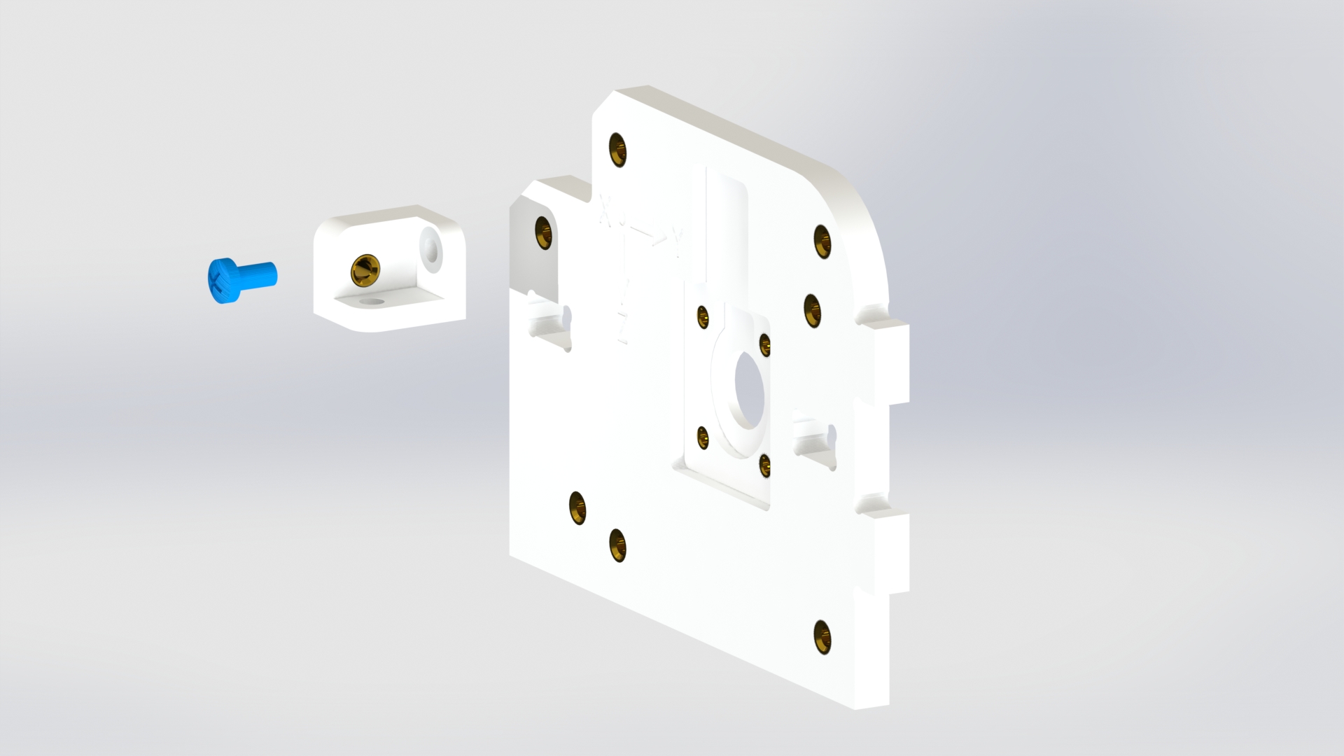
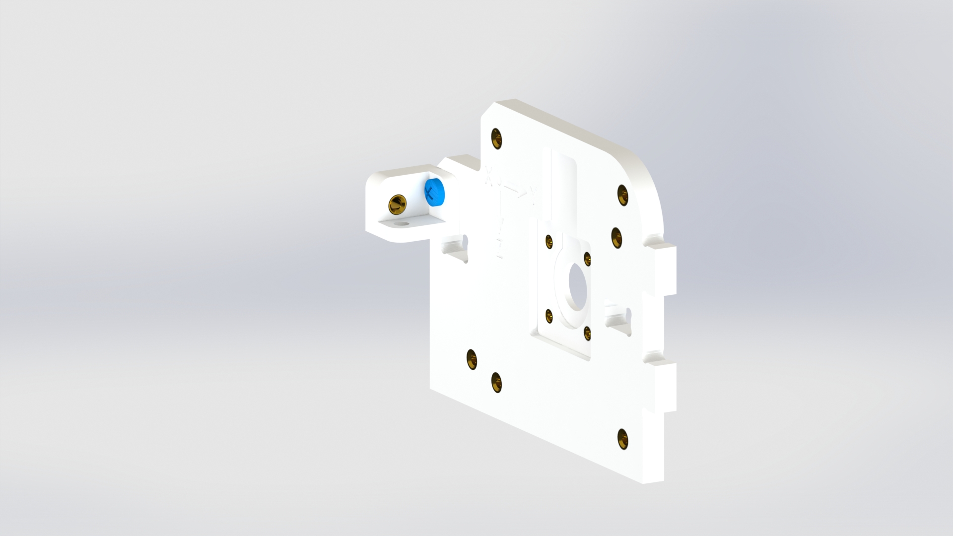
Picture 1.
Attach the encoder board to the housing with four screws M2x4 (picture 2).
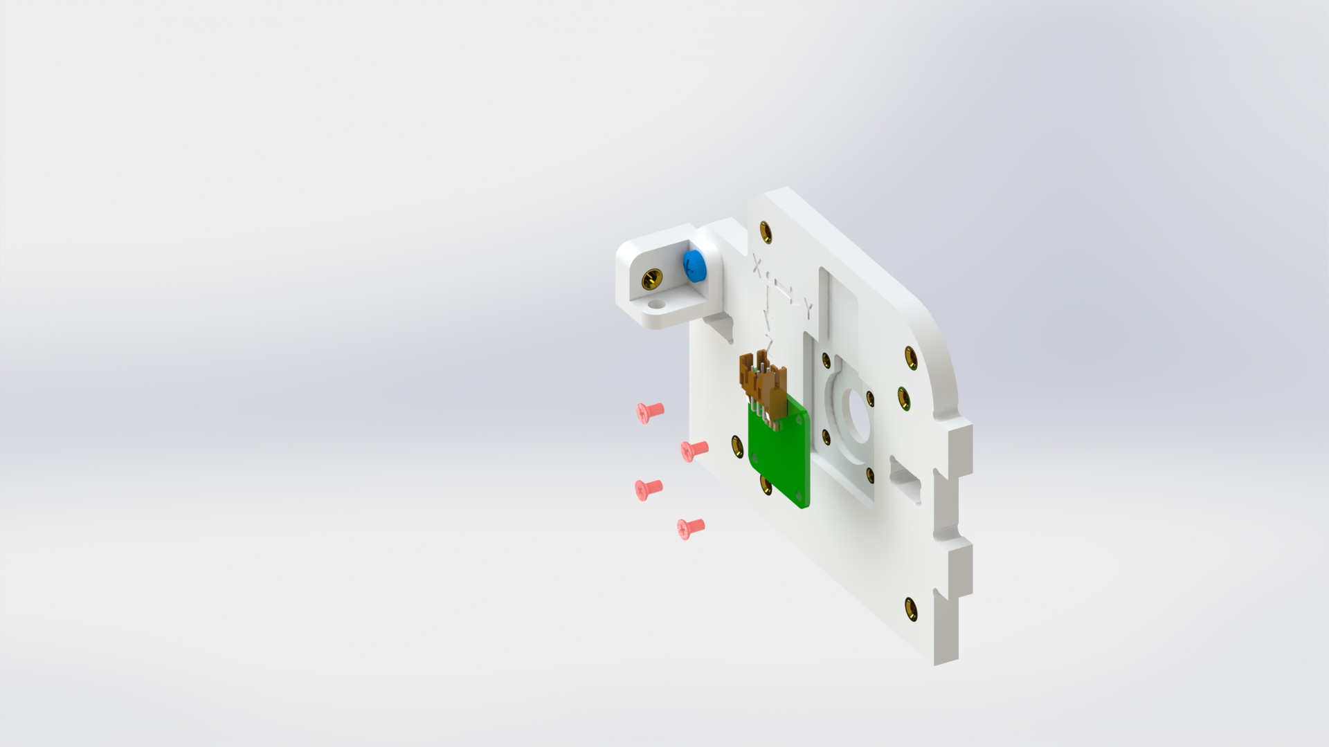
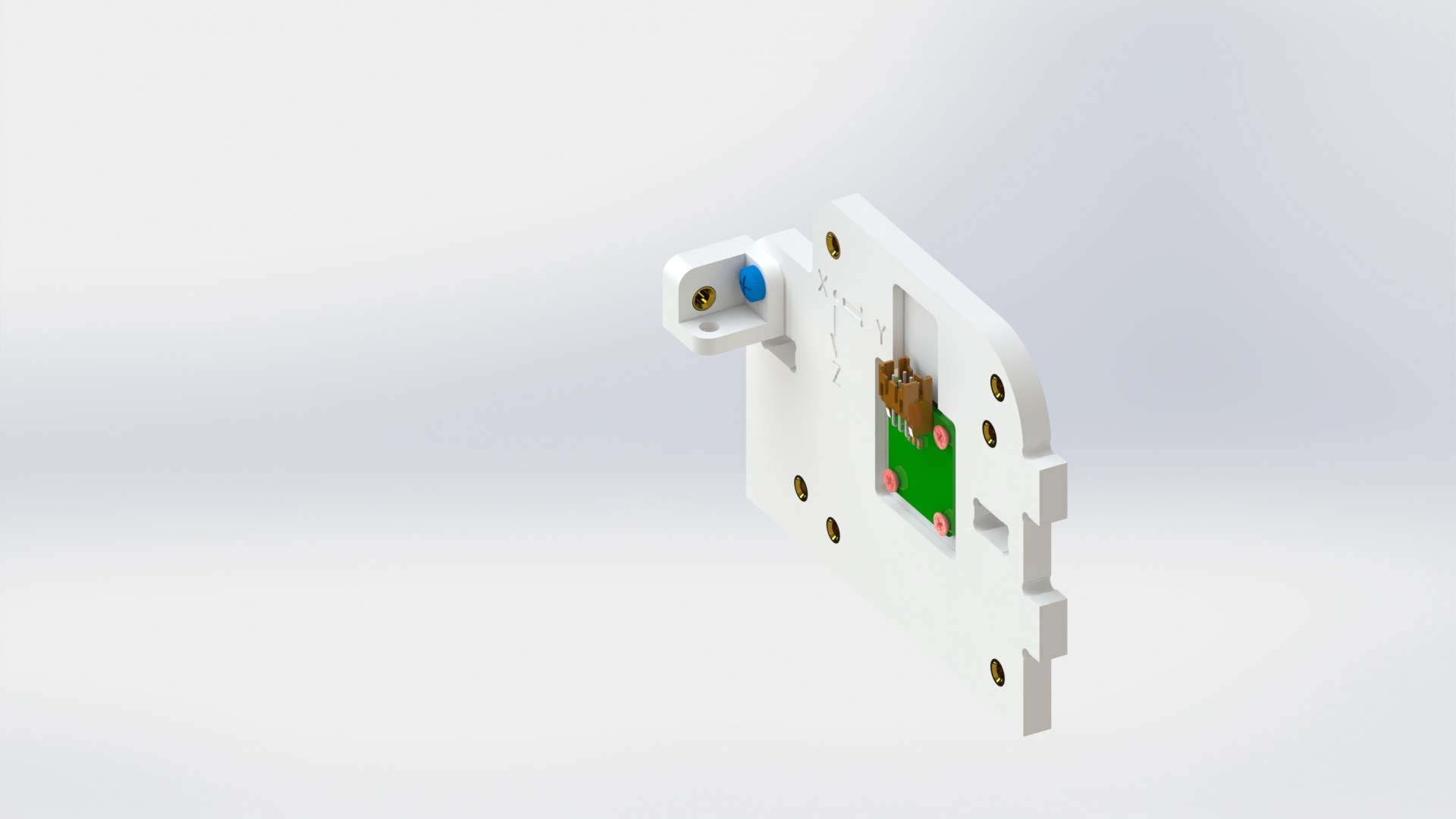
Picture 2.
Attach the angle bracket to the back side of the wall with one screw M3x6 (picture 3).
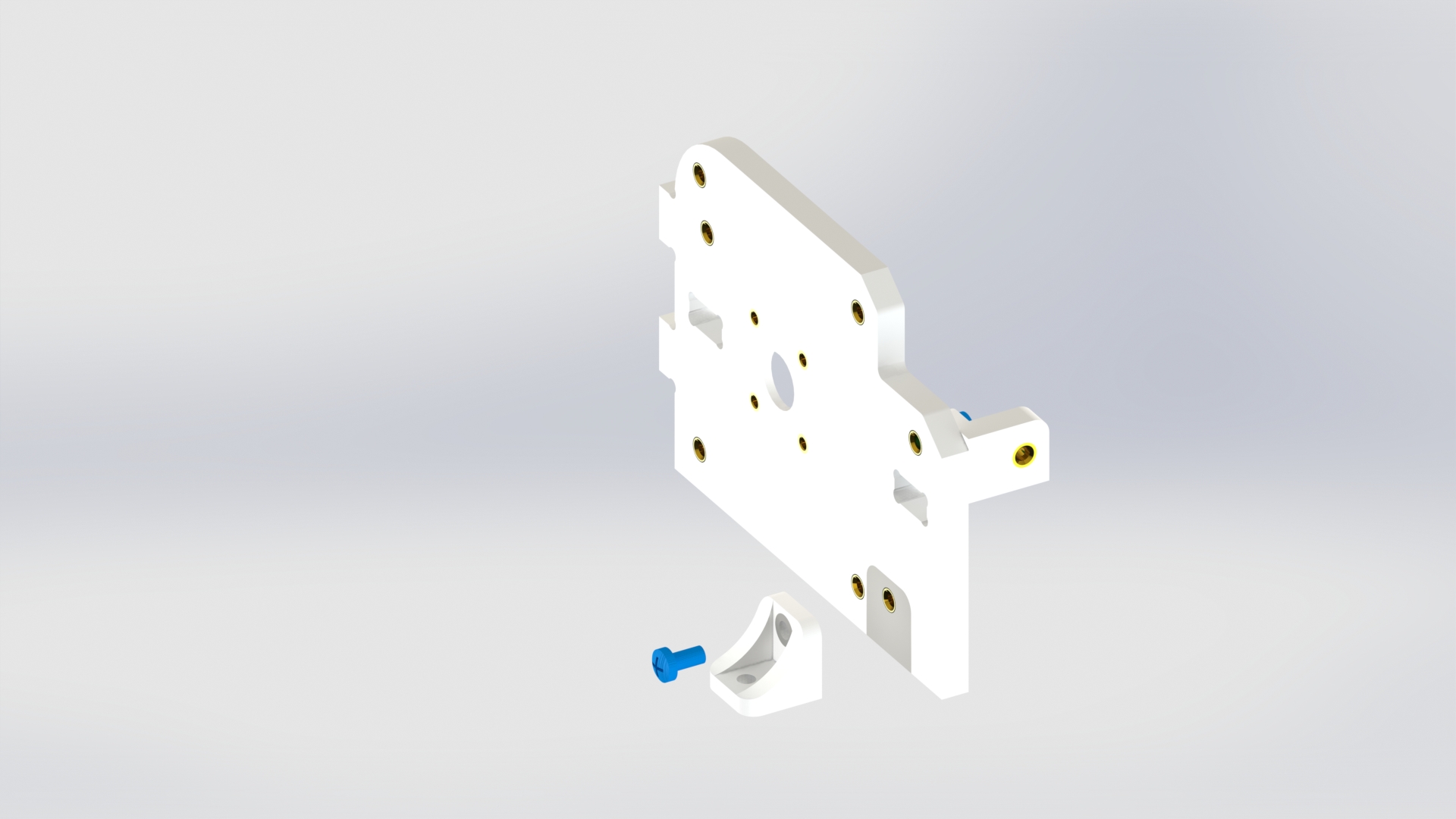

Picture 3.
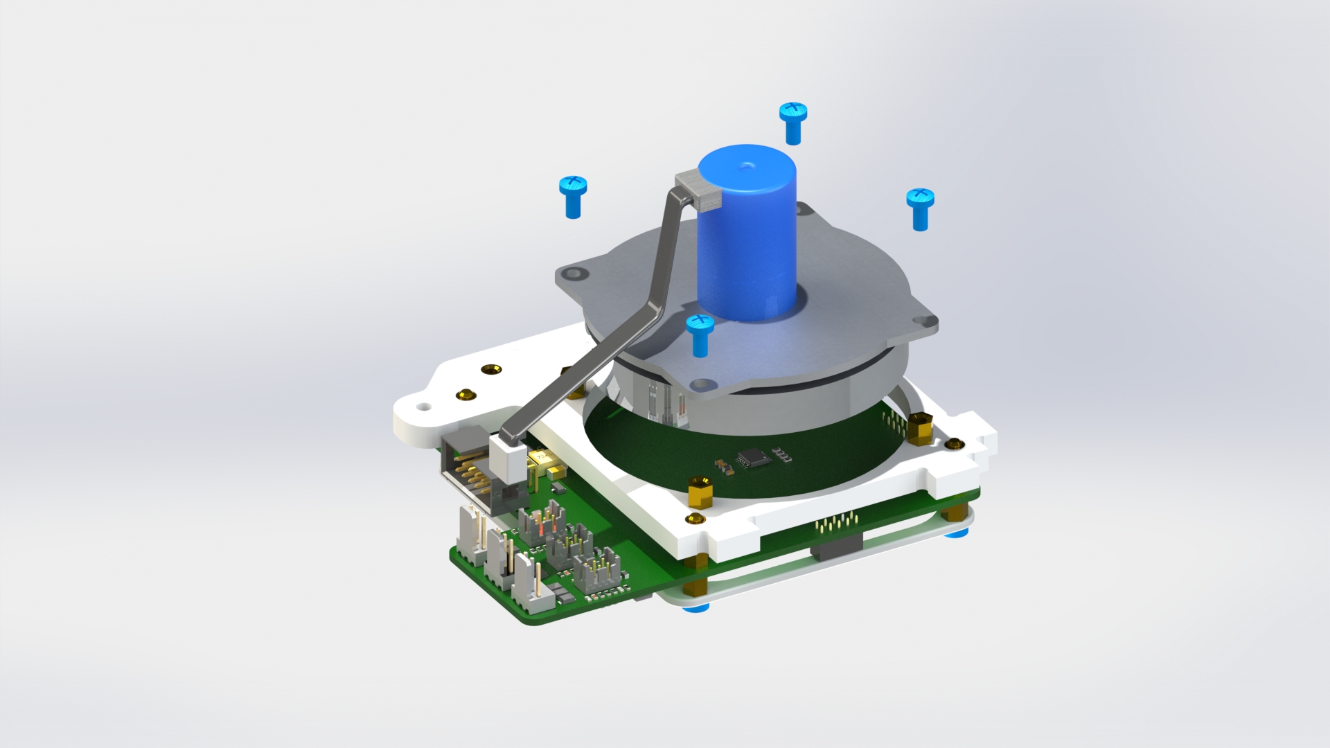
Connect the reaction wheel motor to the housing with four brass standoffs PCHSN-12 and four screws M3x6 (picture 4).
Picture 4.
Assembly of reaction wheel B (for rotating the device around the Y axis)
Attach the angle bracket to the wall on the side where the "Y" axis is engraved with one screw M3x6 (picture 5).

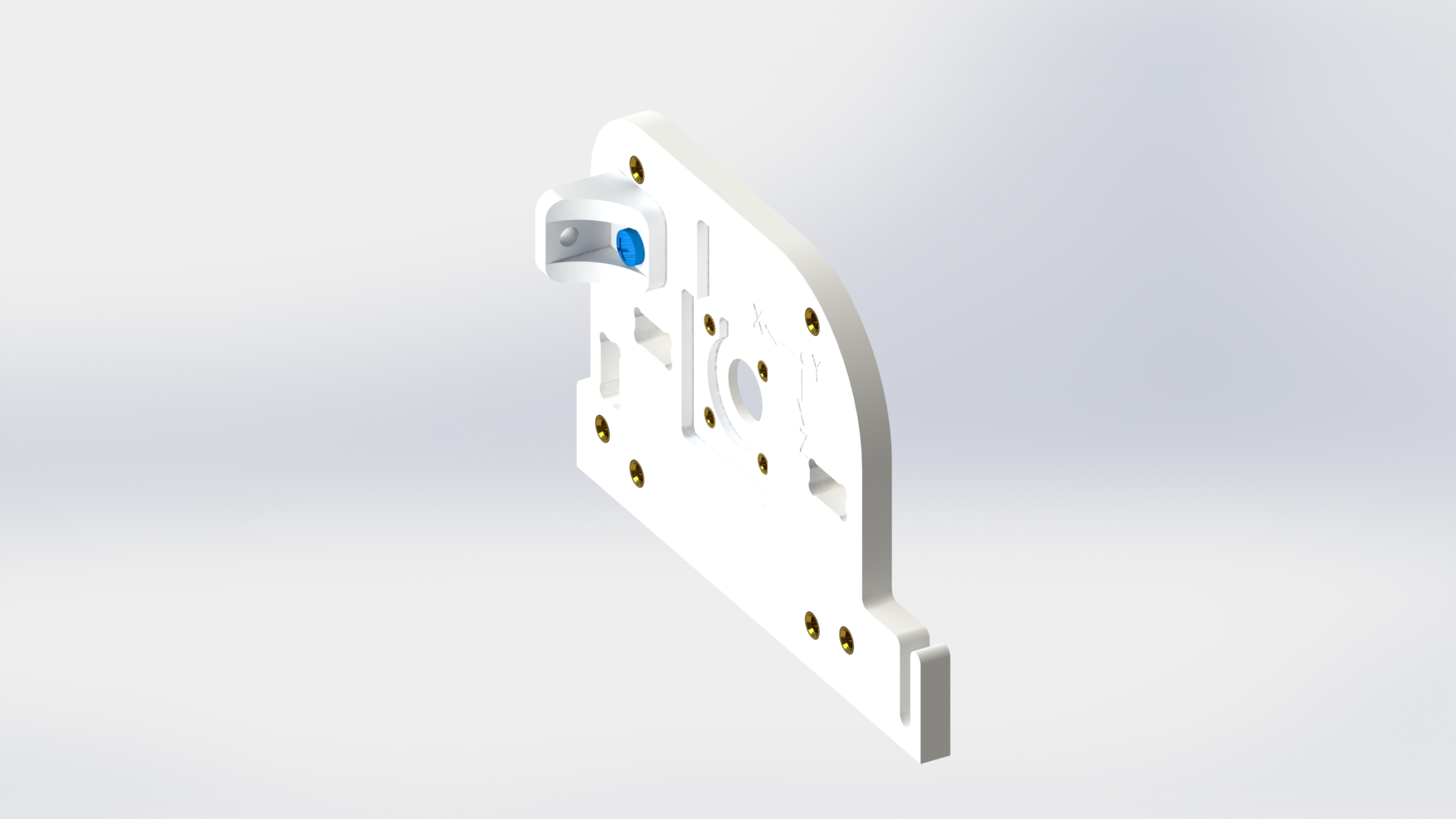
Picture 5.
Attach two angle brackets to the back side of the wall with two screws M3x6 (picture 6).
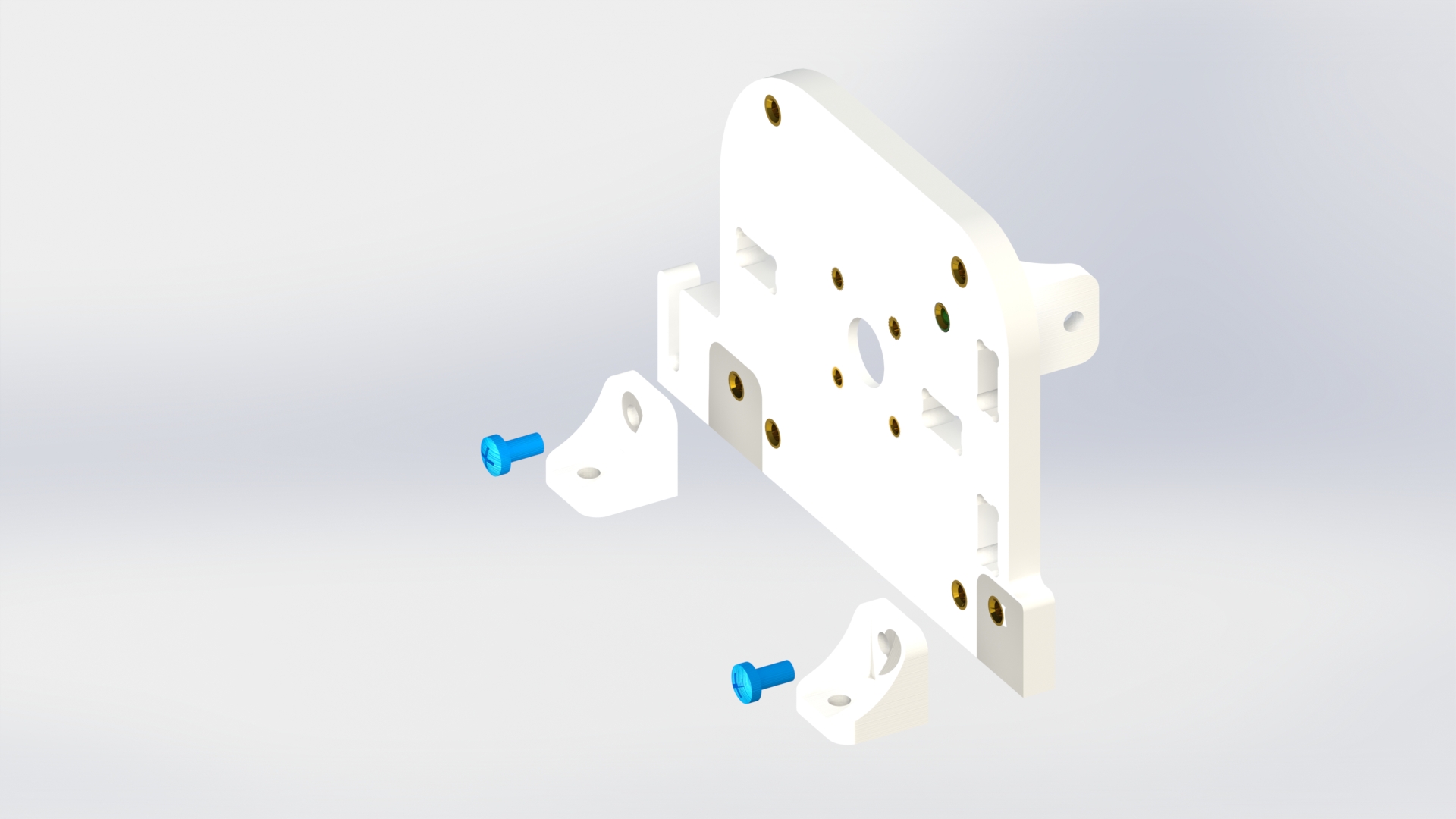
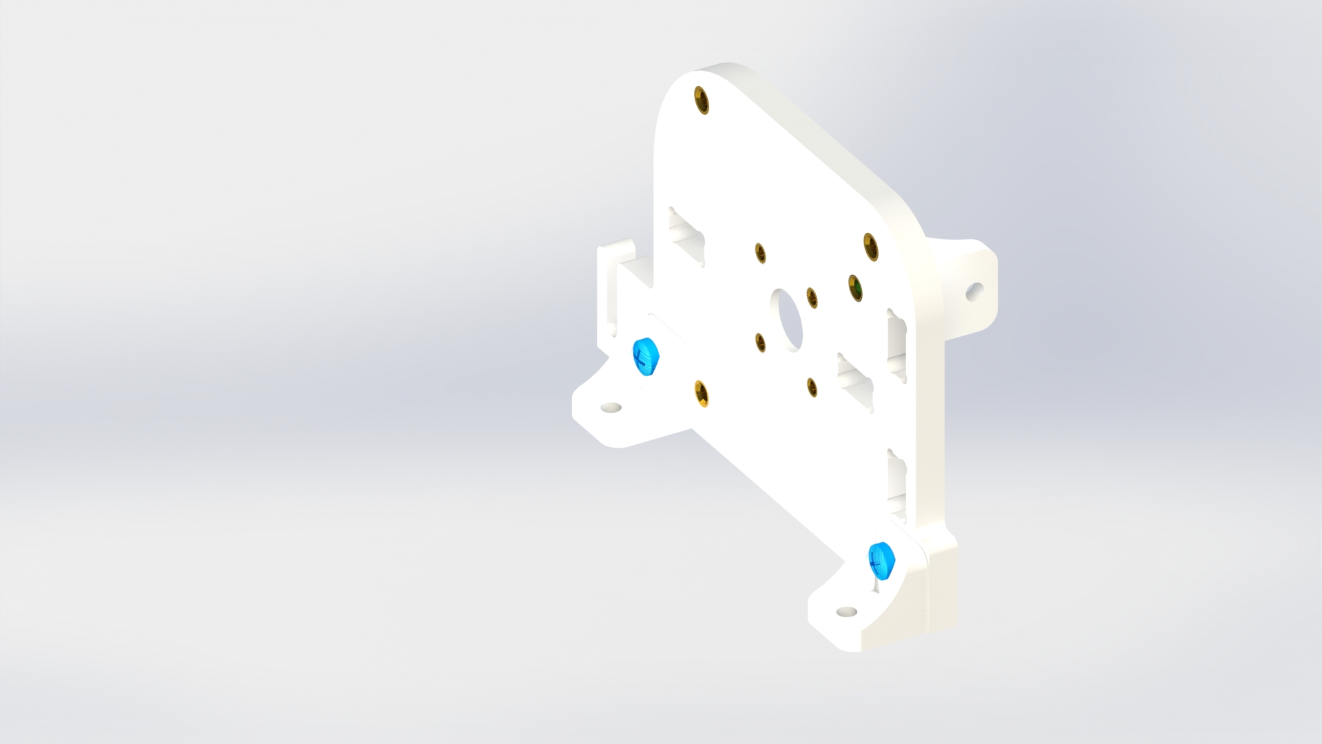
Picture 6.
Attach the encoder board to the housing with four screws M2x4 (picture 7).
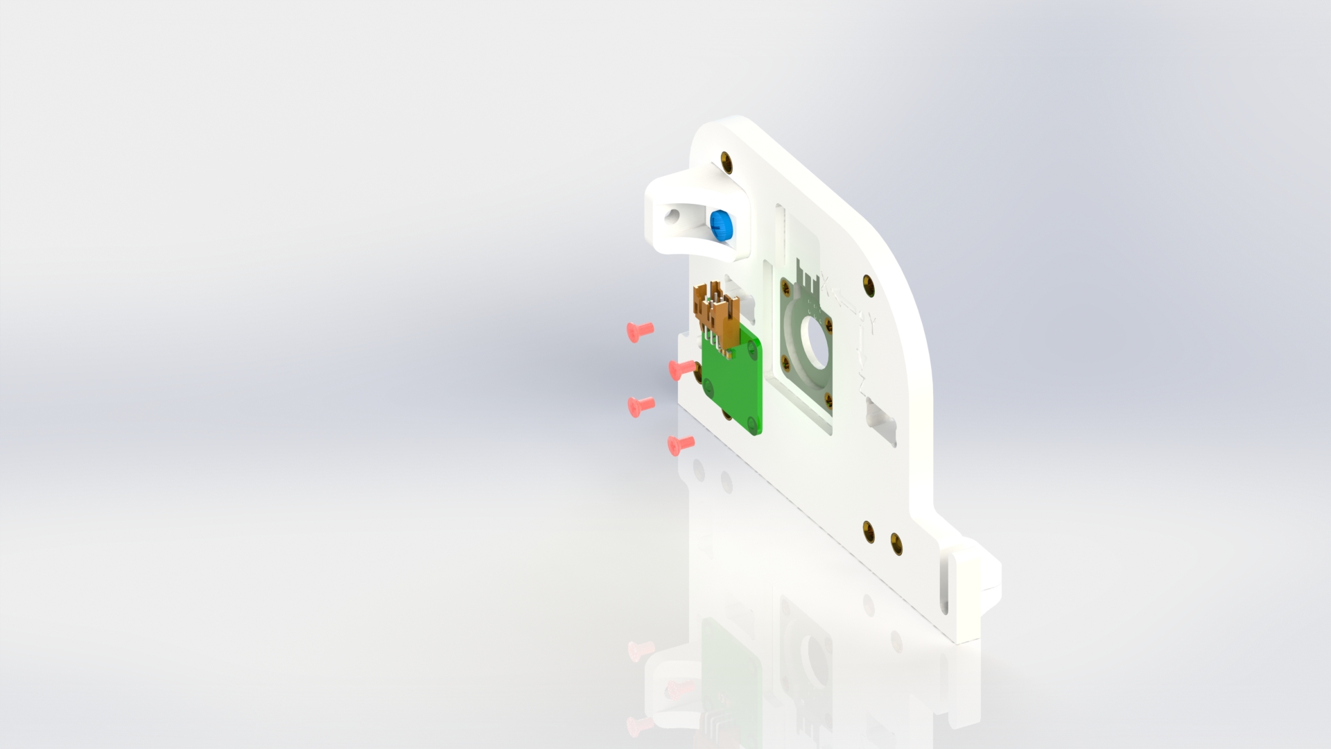
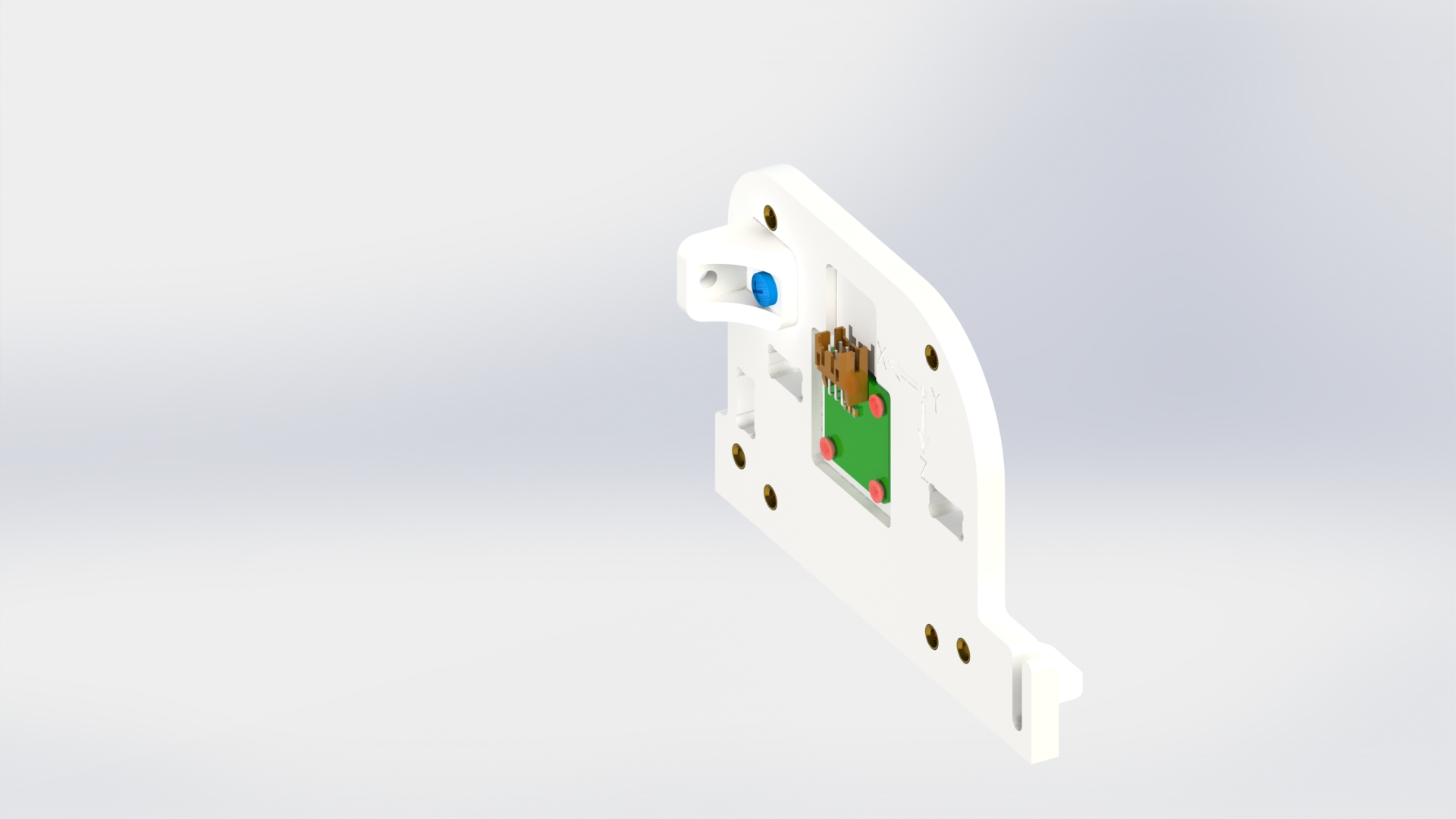
Picture 7.
Screw in four brass standoffs PCHSN-12 behind the encoder board (picture 8).
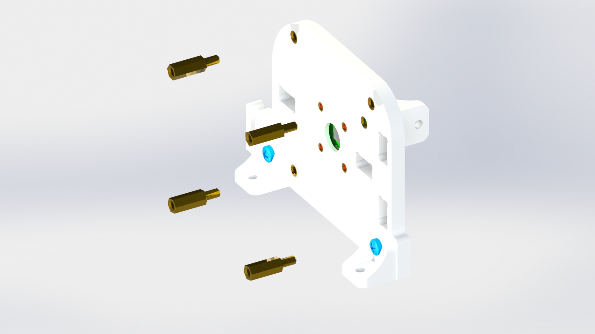
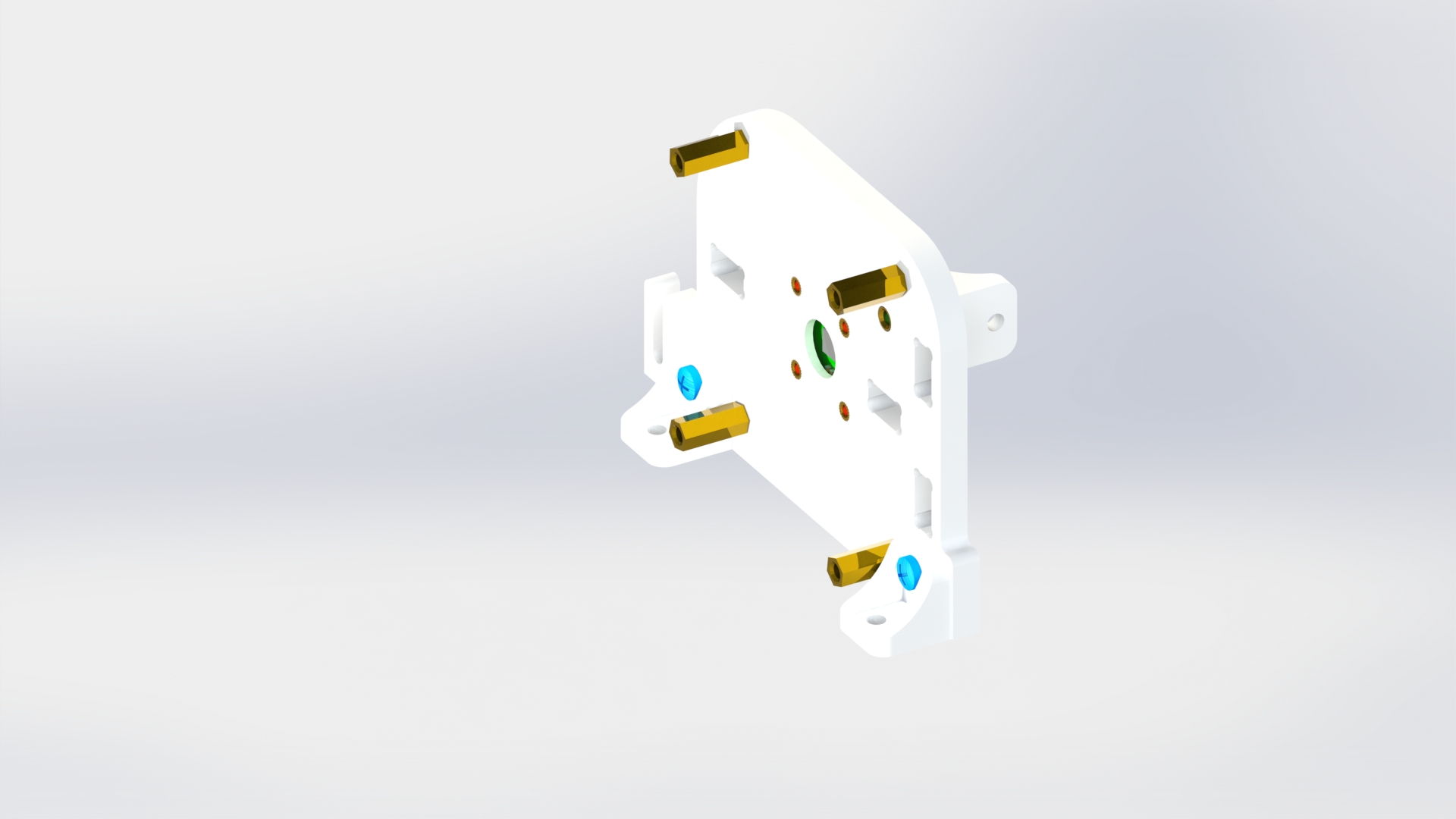
Picture 8.
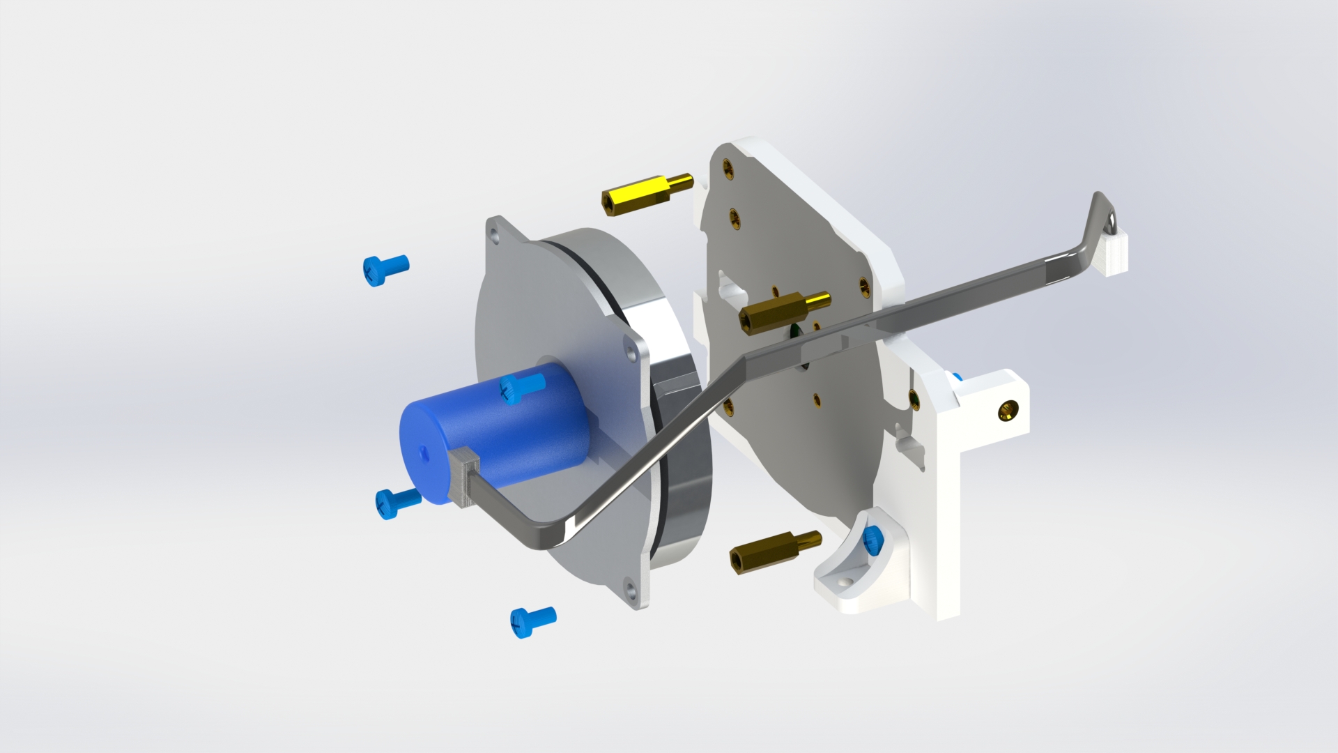
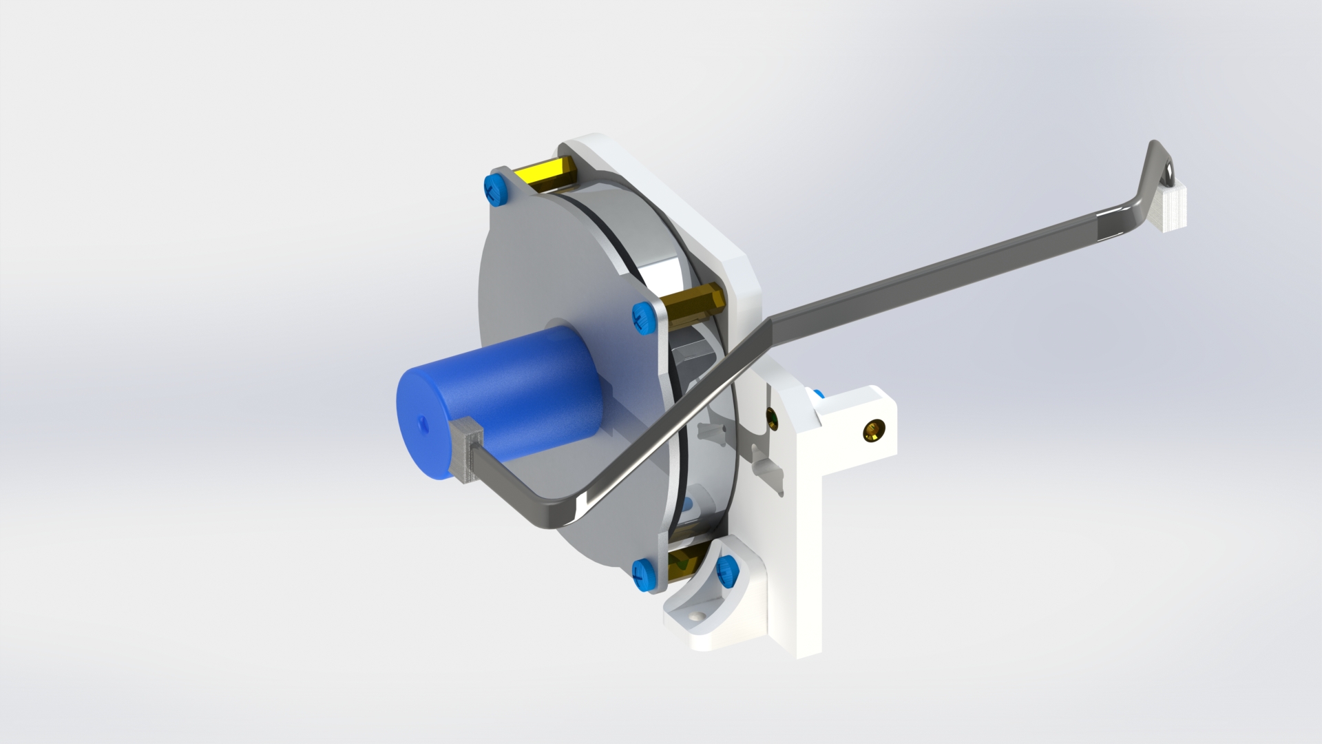
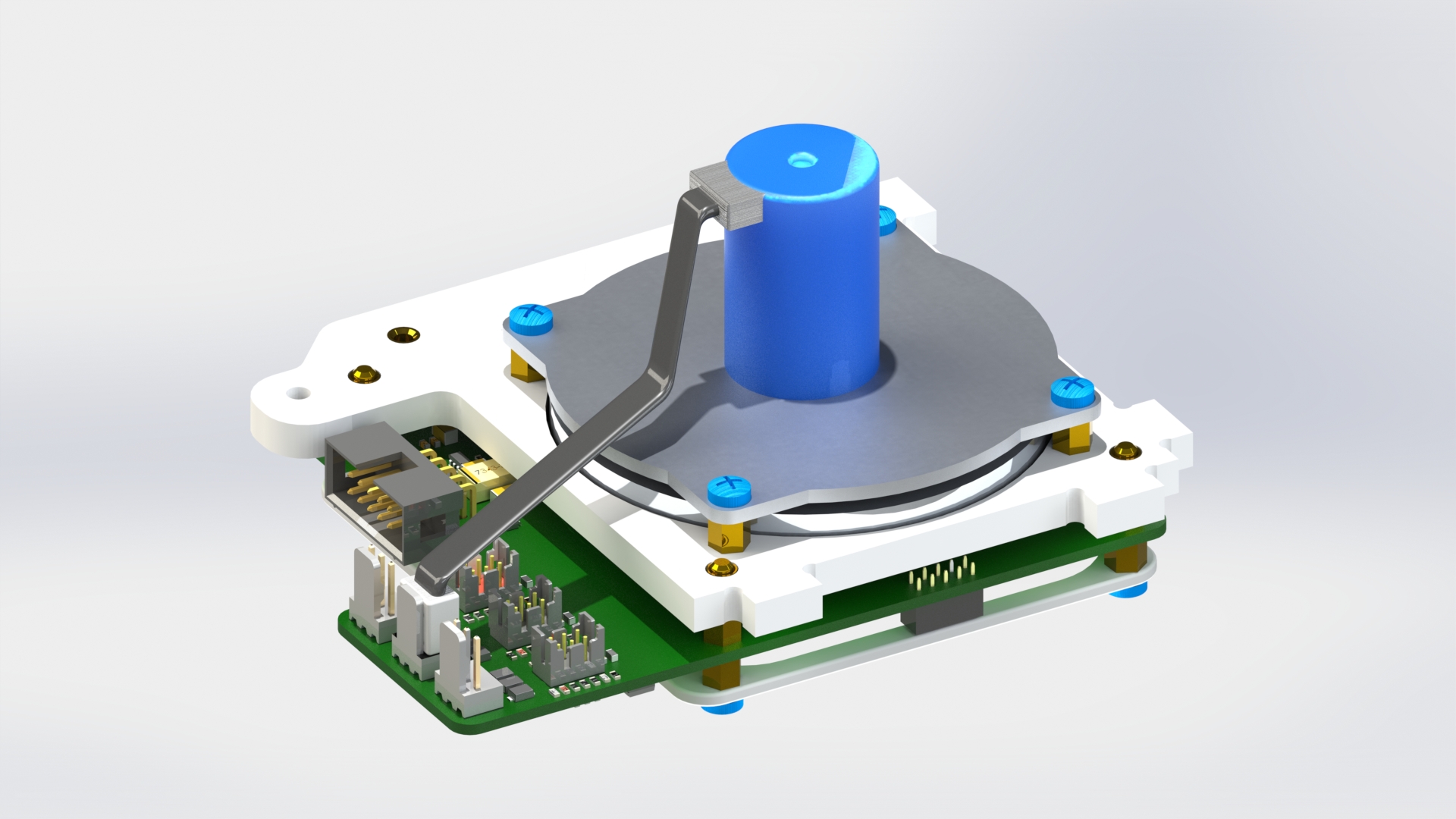
Connect the reaction wheel motor to the housing with four screws M3x6 (picture 9).
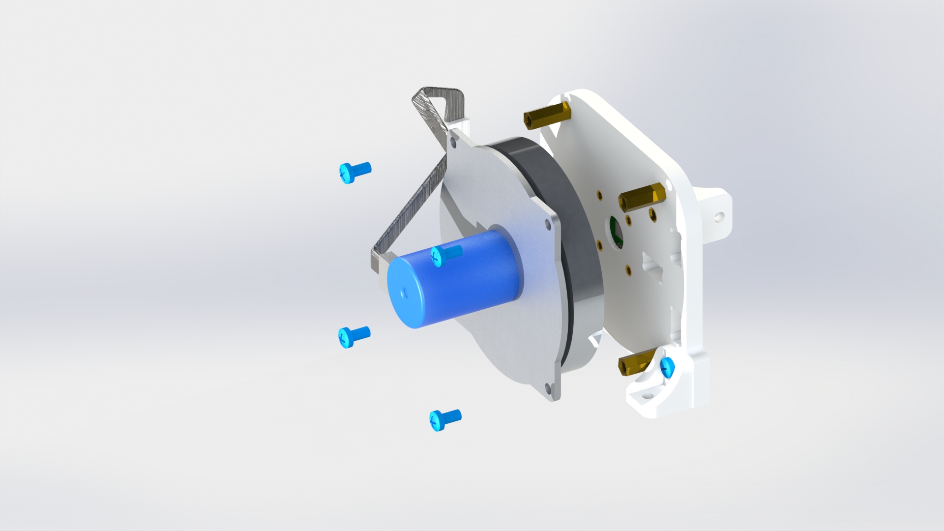
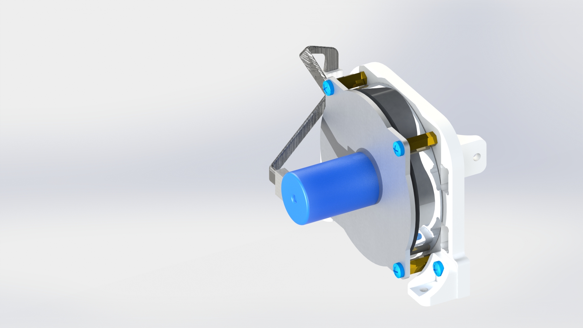
Picture 9.
Assembly of reaction wheel C (for rotating the device around the Z axis)
Attach four brass standoffs PCHSN-5 to the base of the housing (picture 10).
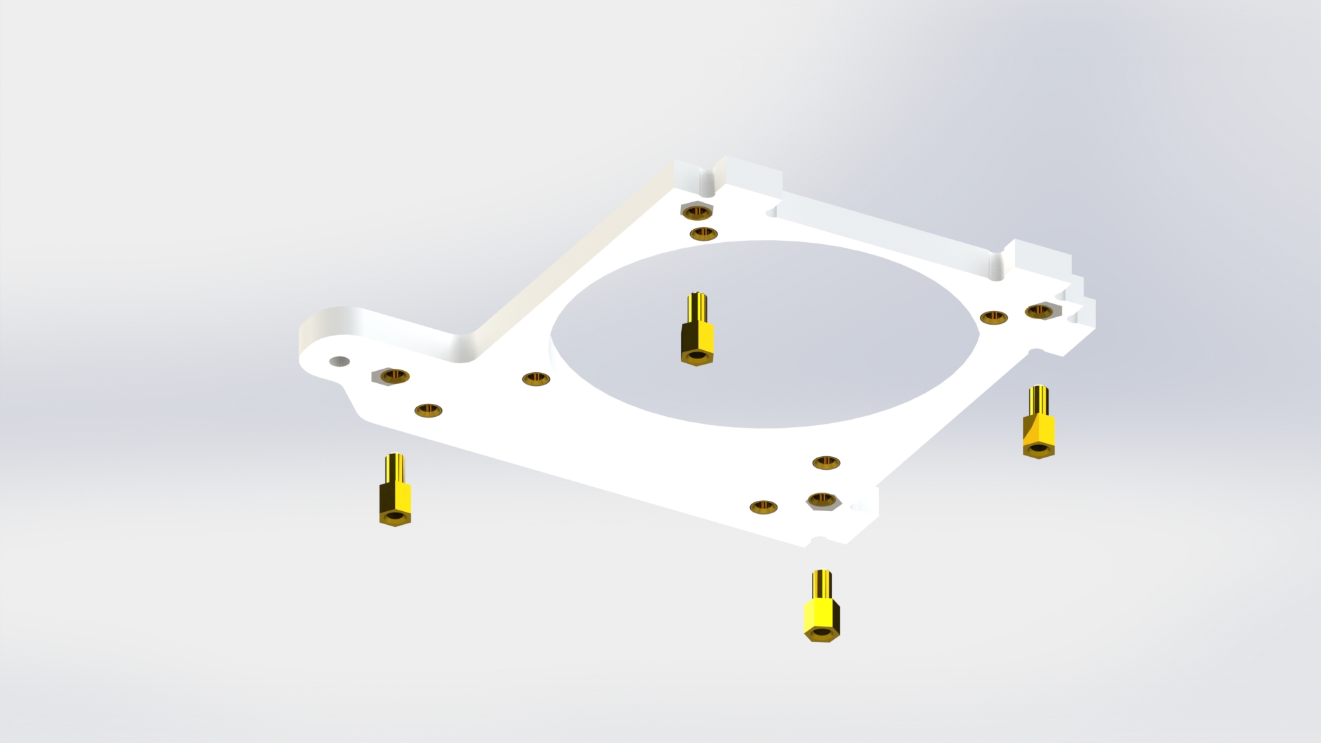

Picture 10.
Connect the frame of the housing to the control motor-reaction wheel board with four brass standoffs PCHSN-5 (picture 11).
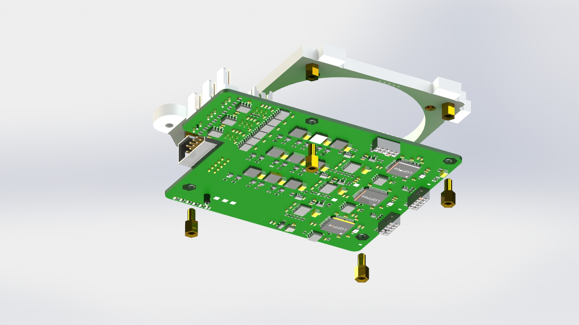
Picture 11.
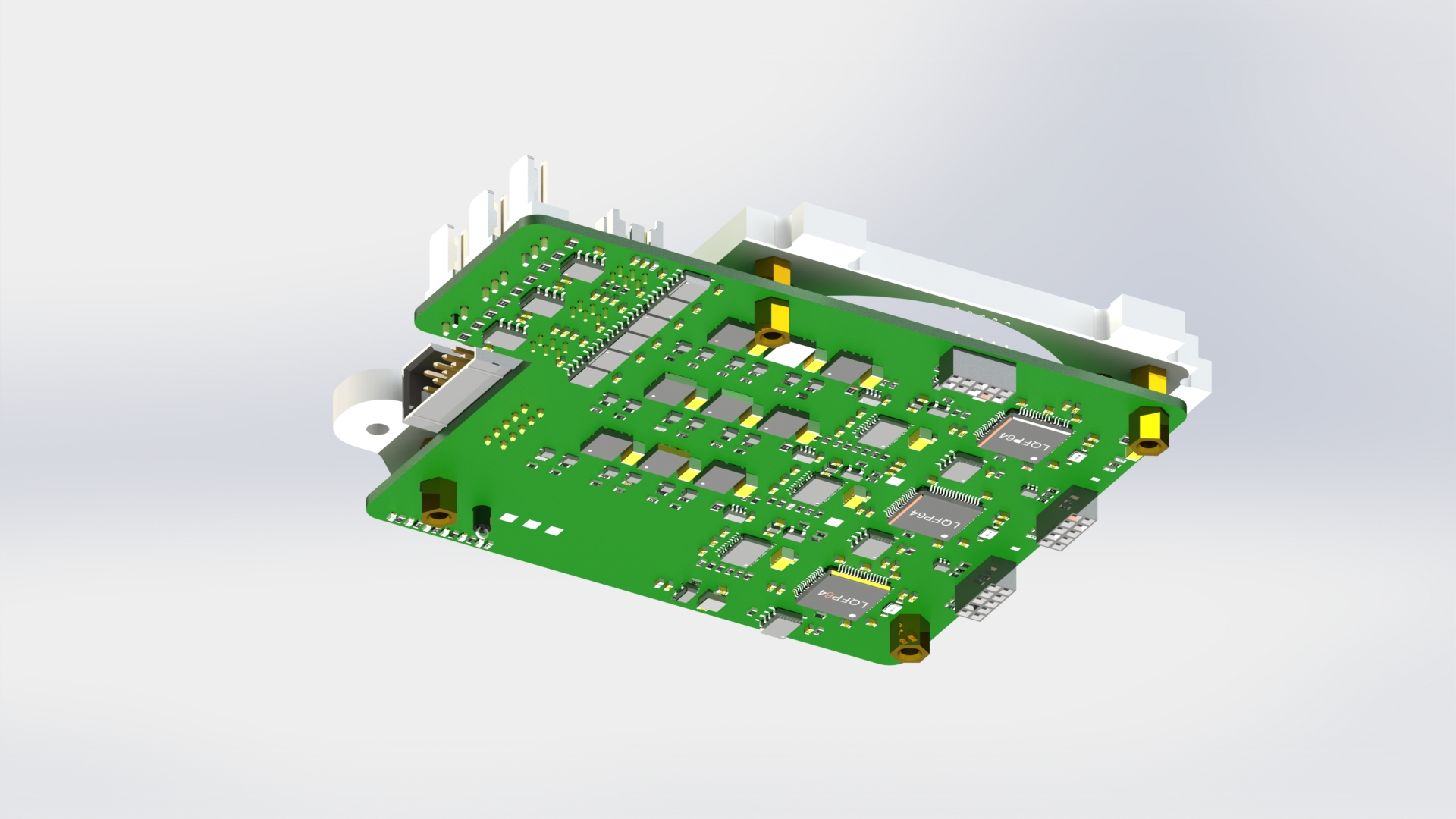
Secure the board with the housing frame using four screws M3x6 (picture 12).

Picture 12.
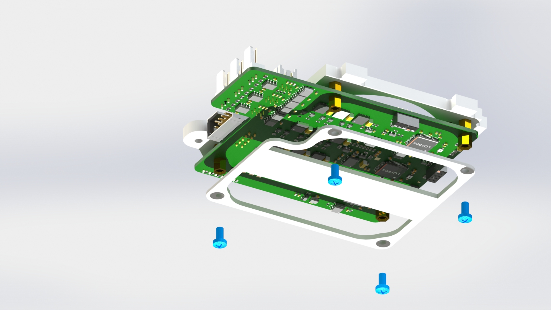
Connect the reaction wheel to the base with four screws M3x6. Connect the reaction wheel ribbon cable to the central connector on the board (picture 13).
Picture 13.
Connect the angle bracket to the base with one screw M3x6 (picture 14).

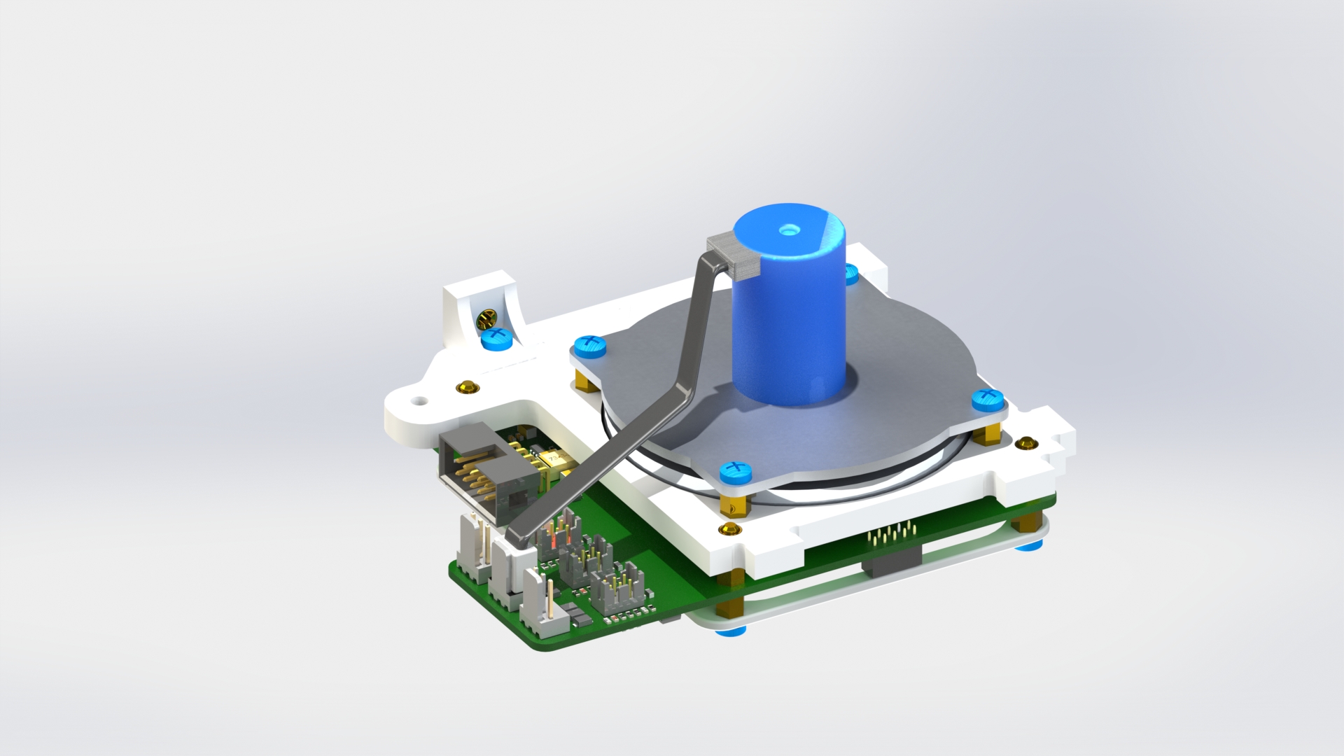
Picture 14.
Assembly of the power system
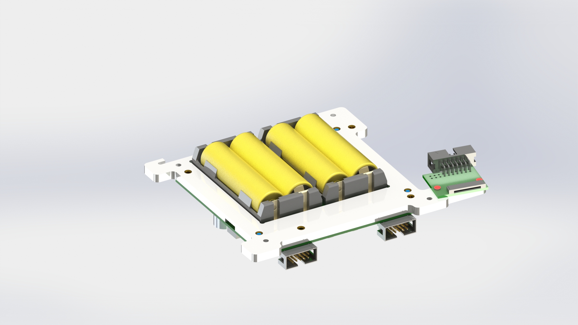
Use three M3x6 screws to attach the power system board to the housing so that the area for the battery packs is located in the cutout (picture 15).


Picture 15.
Insert four batteries into the connectors, observing polarity (the "+" sign on the battery corresponds to the "+" sign on the connector, and similarly for the "-" signs) (picture 16).

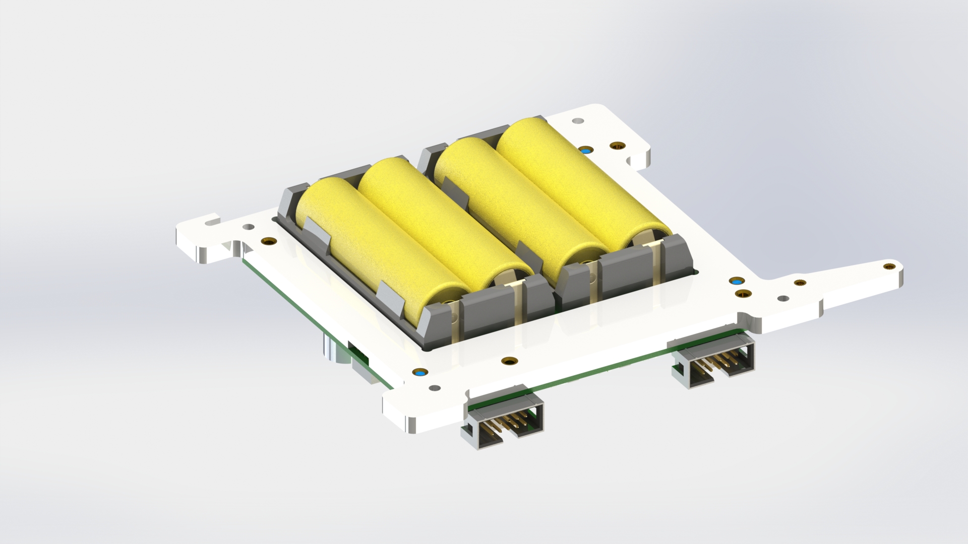
Picture 16.
Use two M2x4 screws to connect the camera adapter board to the convex part of the base (picture 17).
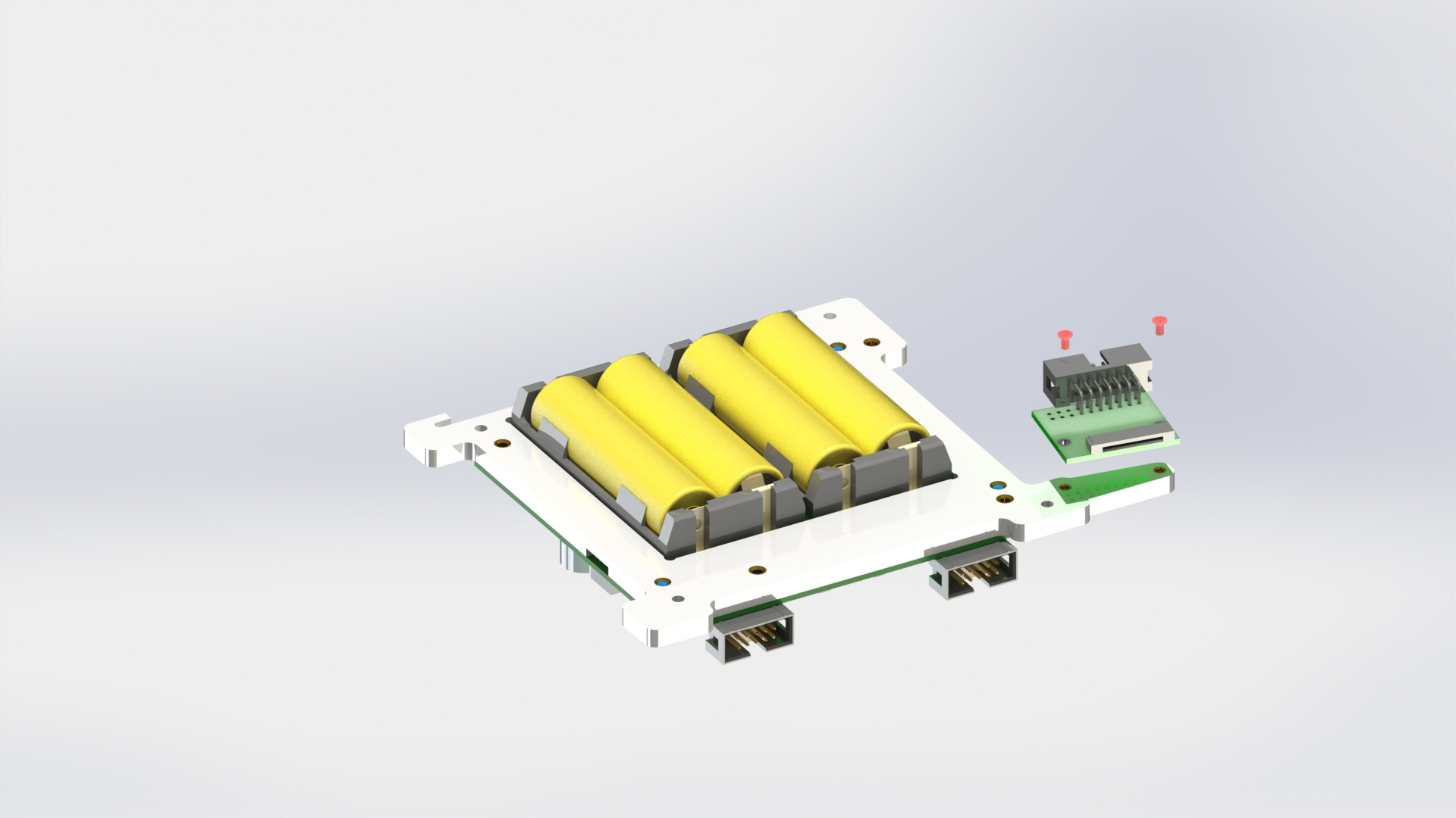
Picture 17.
General assembly
Connect reaction wheel block A to reaction wheel block C using an M3x6 screw through the bracket. Connect the cable of reaction wheel A to the left connector on the encoder board (picture 18).

Picture 18.
Connect reaction wheel block B to reaction wheel block C using an M3x6 screw through the bracket. Connect the cable of reaction wheel B to the nearest connector to the block (picture 19).
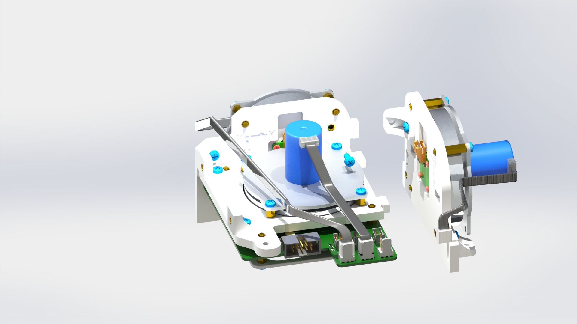

Picture 19.
Screw an M3x10 screw with a brass stand PCHSS-30 into the protruding angle on the housing of block C (picture 20).
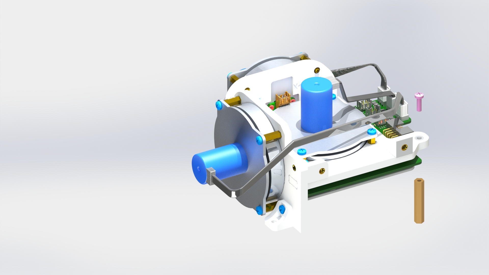
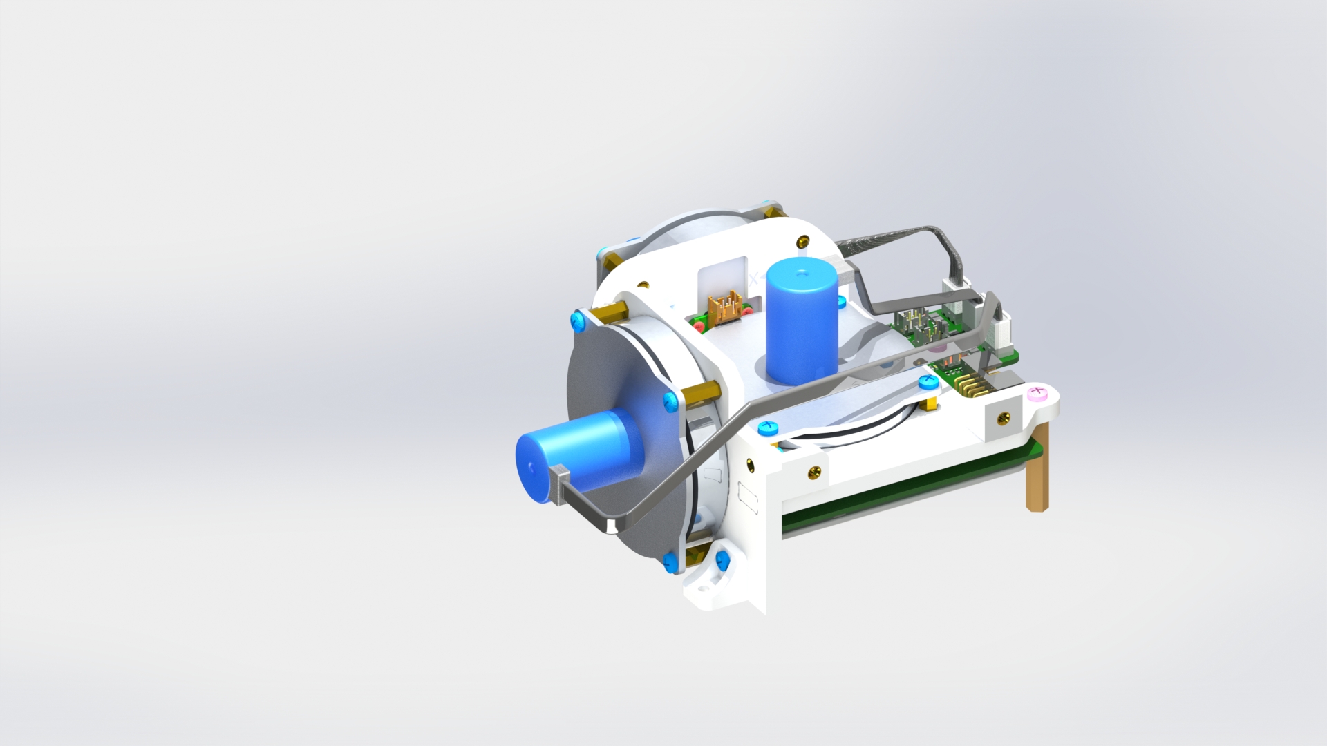
Picture 20.
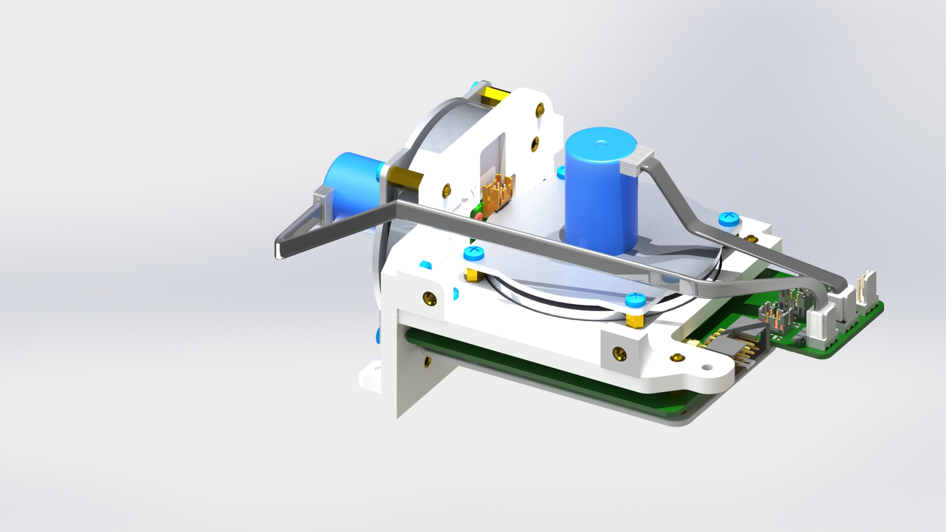
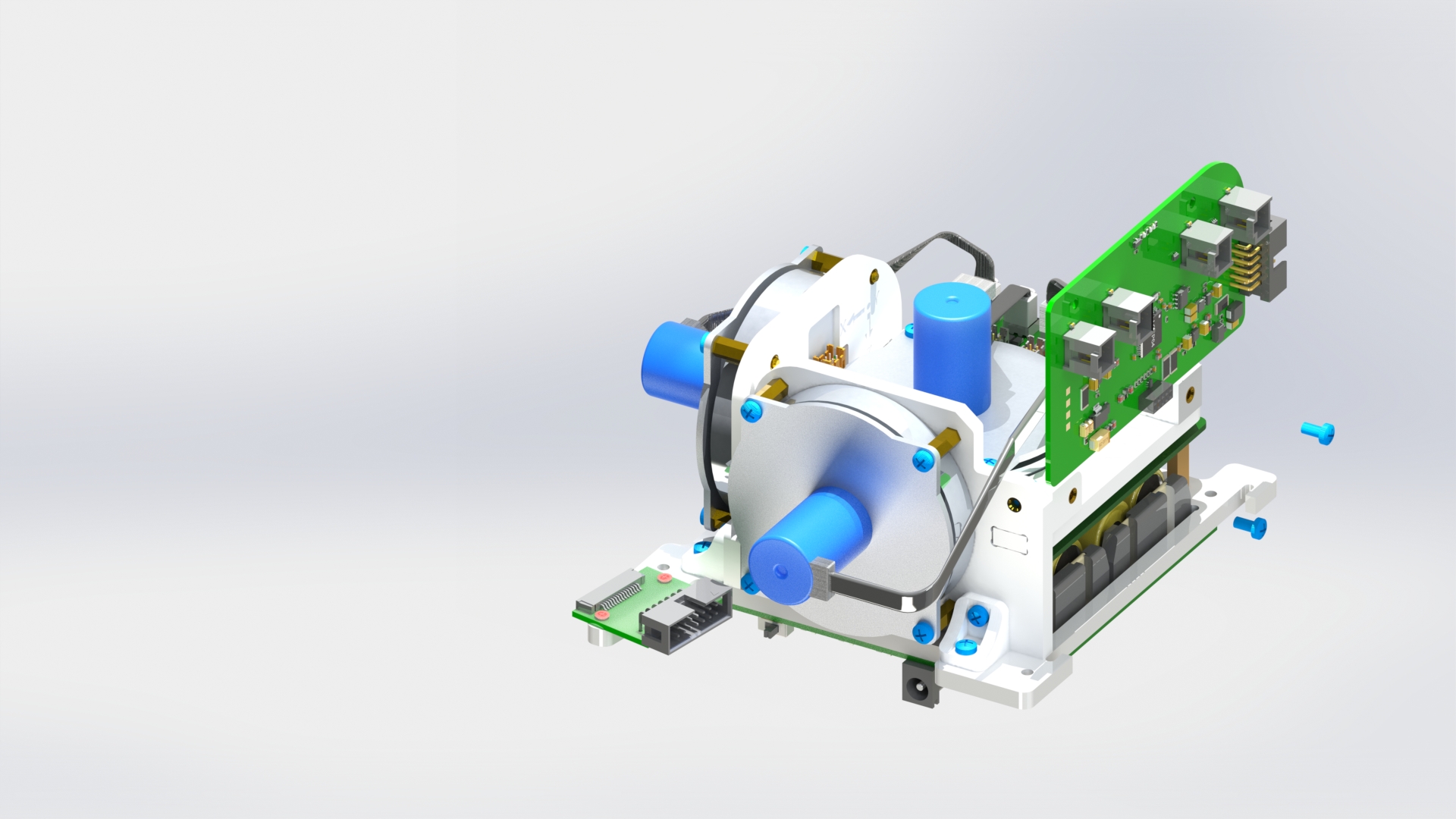
Connect the reaction wheel block to the power system block using three M3x6 screws and one M3x10 screw through the brackets (picture 21).
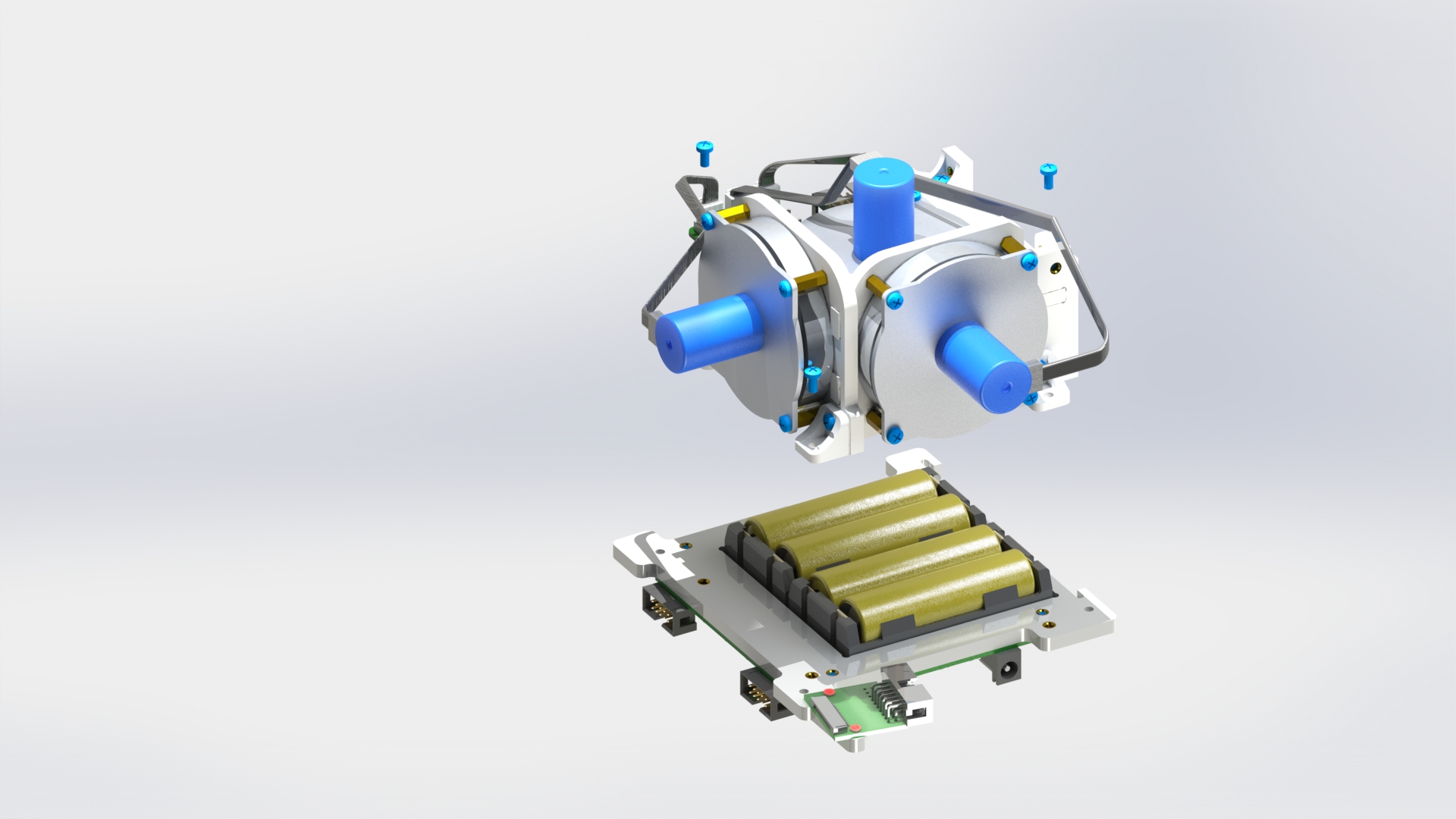

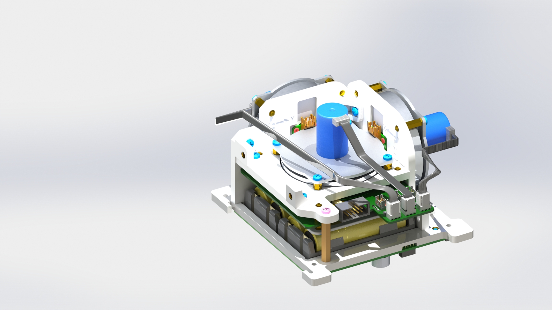
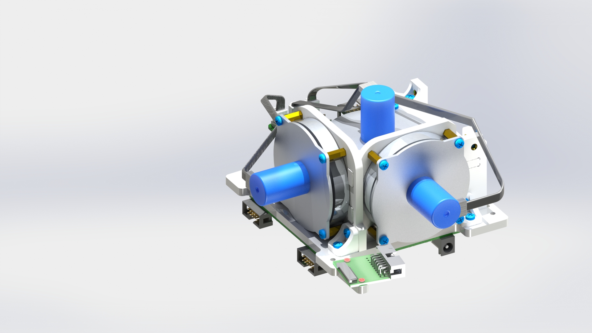
Picture 21.
Connect the solar sensor board to the module using two M3x6 screws (picture 22).
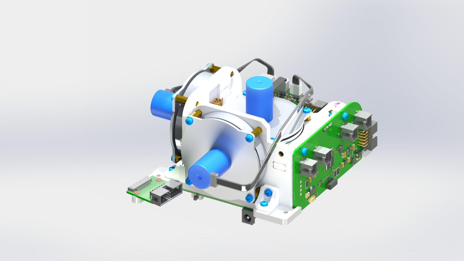
Picture 22.