OrbiX assembly instruction (three-axis configuration)
Components required for assembly:
- Lower part (three-axis) – 1 pc.;
- Middle part – 1 pc.;
- Upper part – 1 pc.;
- Transparent hemispheres – 2 pc.;
- Screw М3х6 – 10 pc.;
- Screw М3х10 – 8 pc.;
- Screw М3х20 – 1 pc.;
- Screw with ring.
Assembly order
Нижнюю часть корпуса соединить со средней с помощью четырех винтов М3х10 (picture 1).


Picture 1.
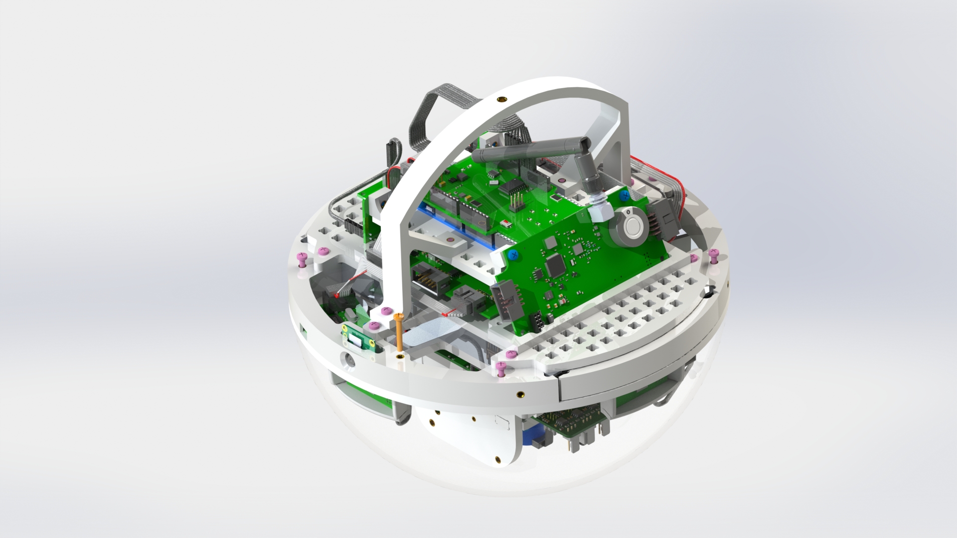
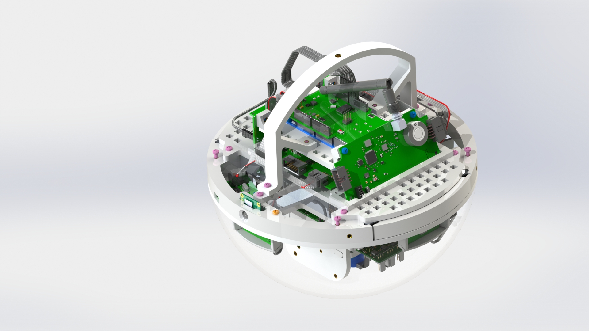
Connect the upper part to the middle one using two M3x10 screws on the handle (picture 2).
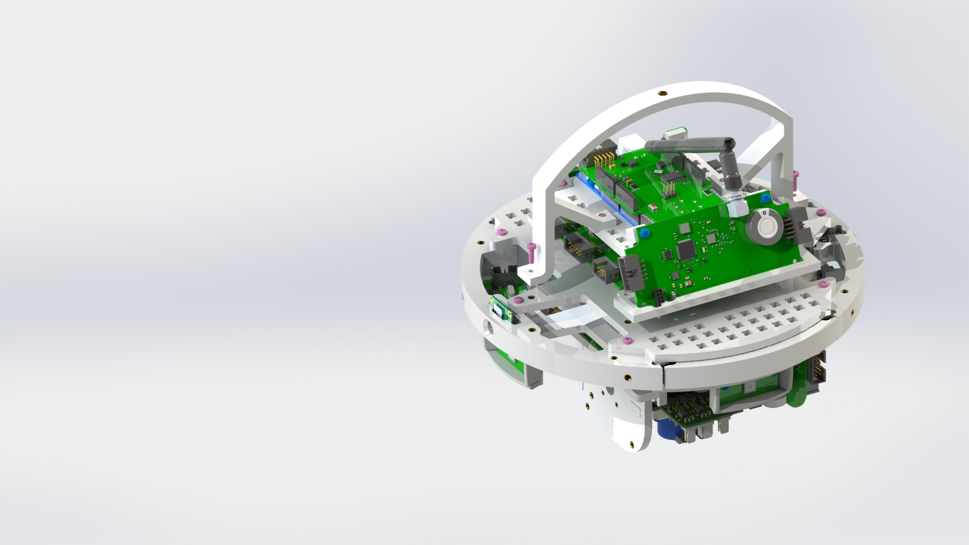
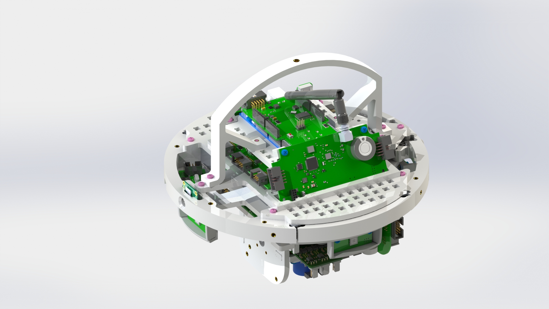
Picture 2.
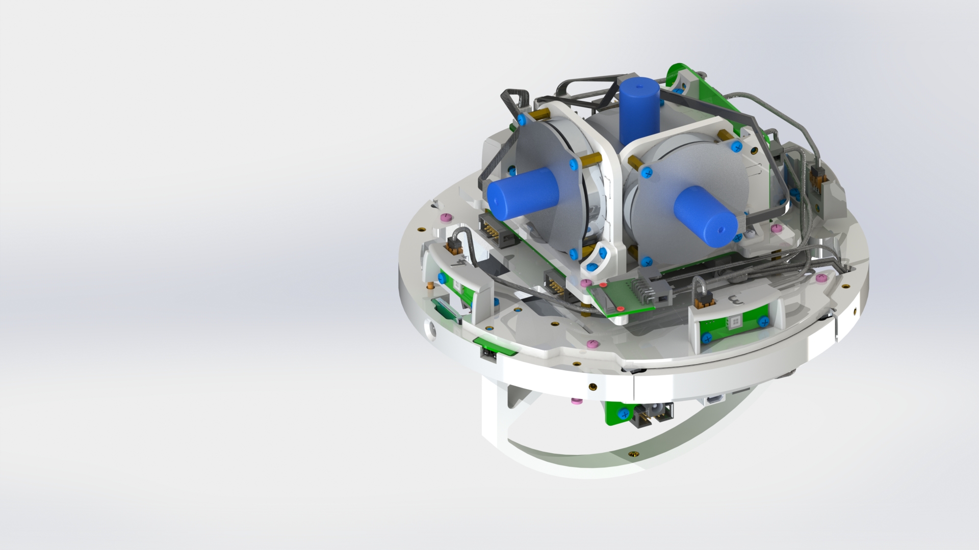
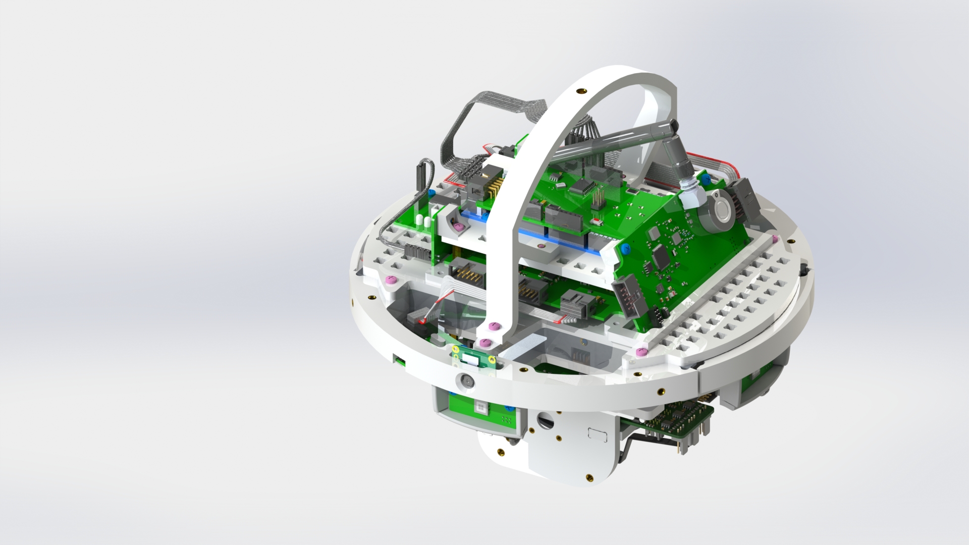
On the lower part, alternately, from right to left, connect the solar sensors to the solar sensor board on the reaction wheel unit (picture 3).
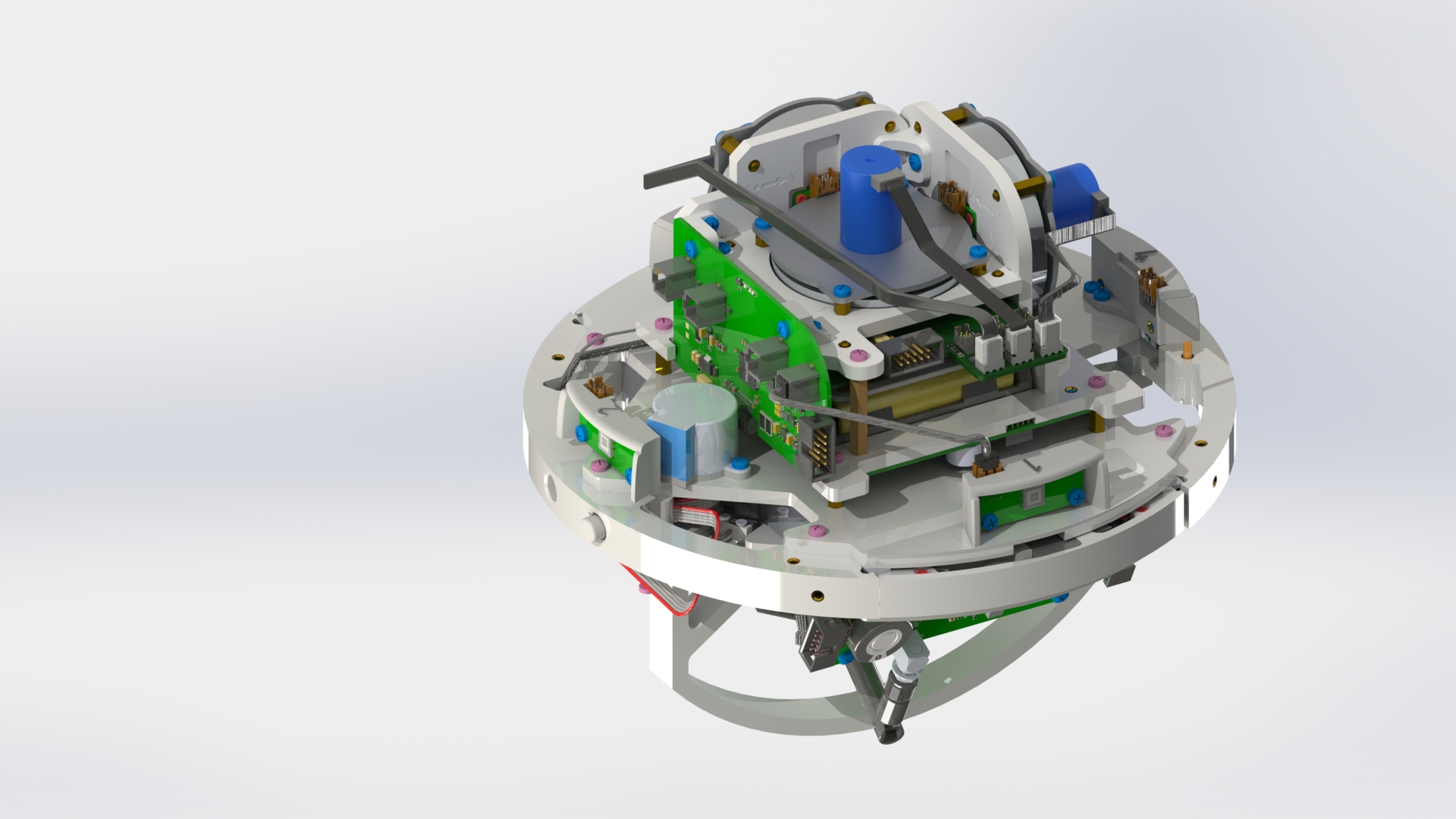


Picture 3.
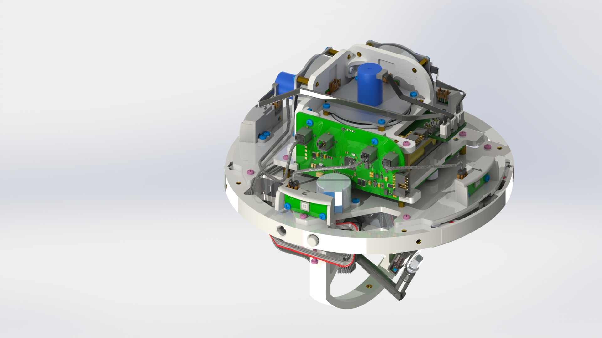
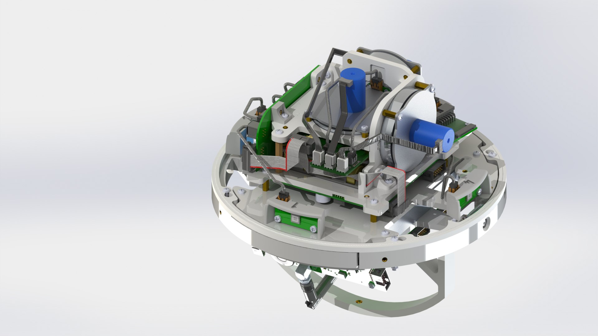
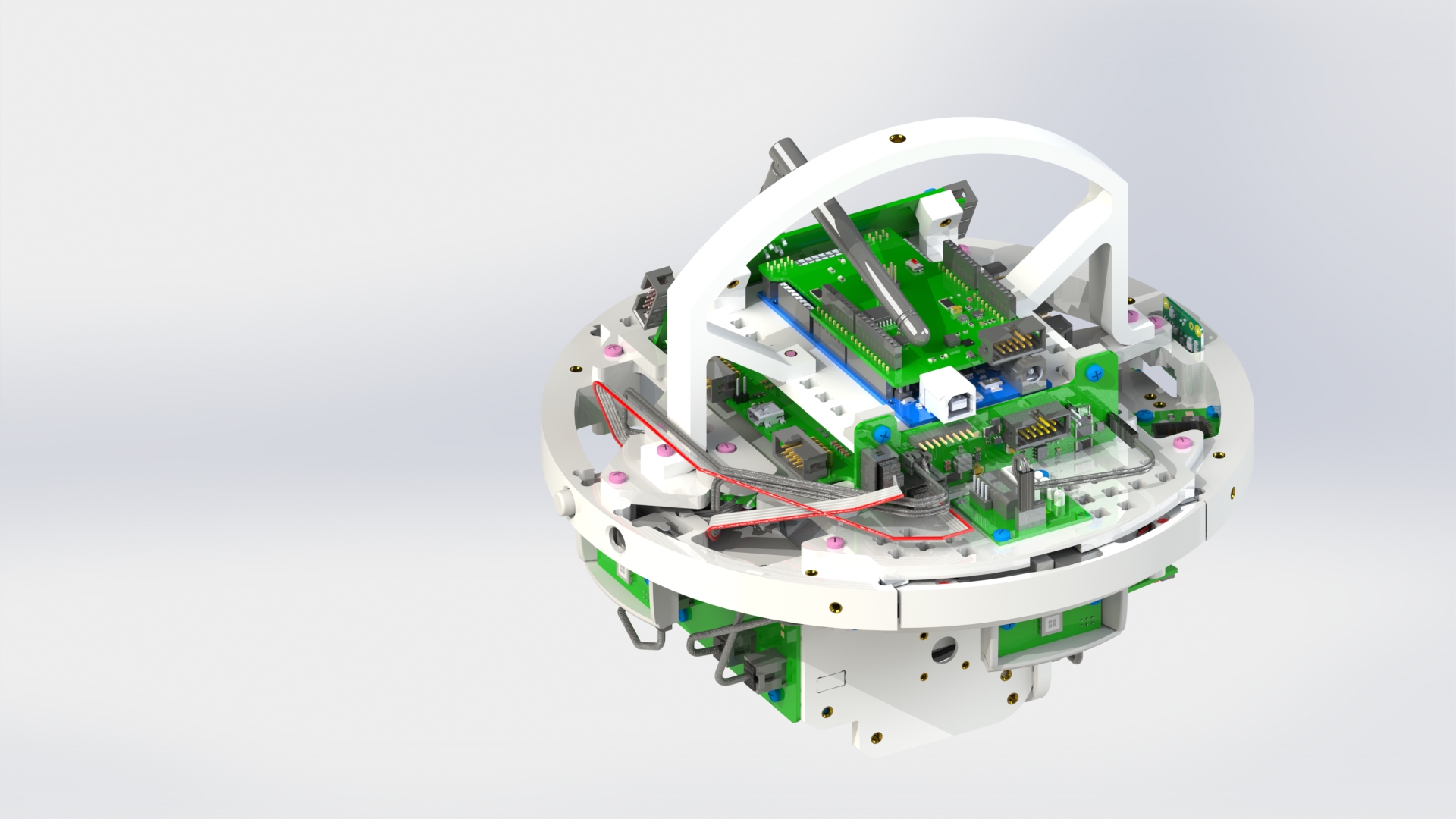
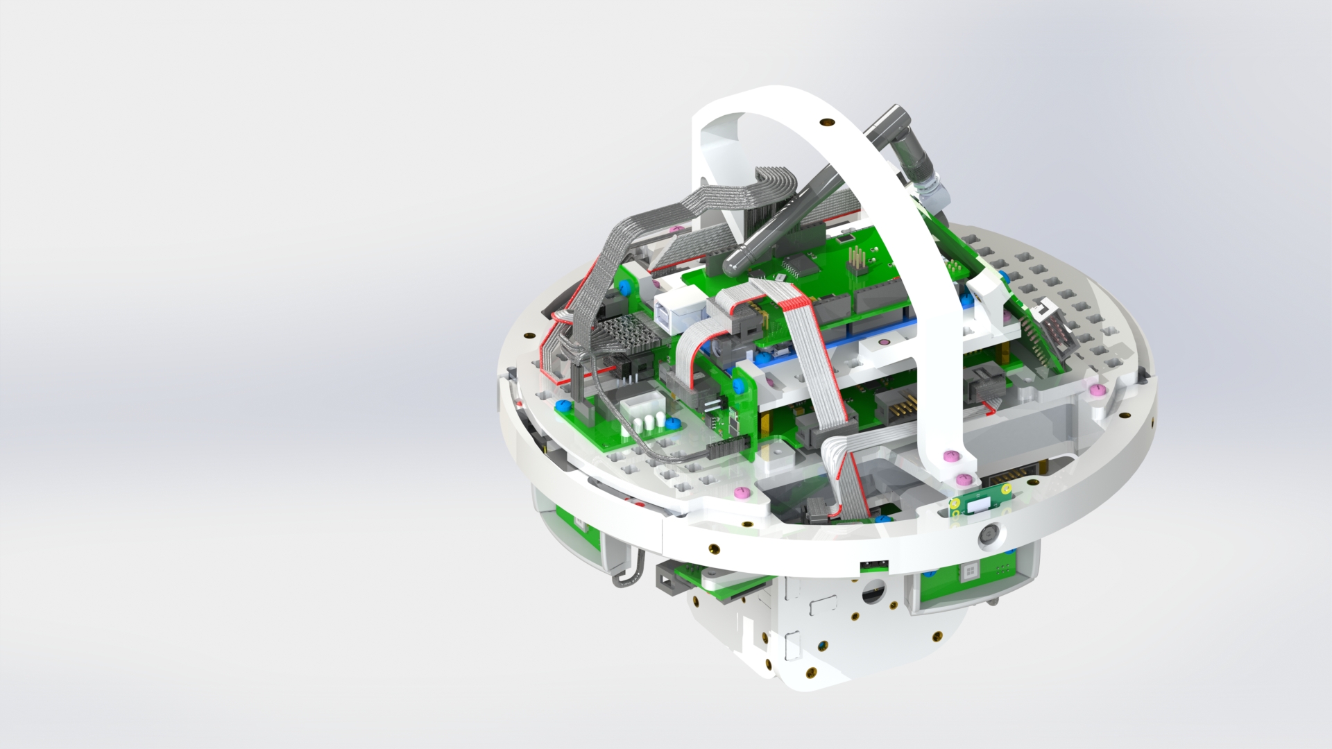
Connect the cables to the camera adapter board (picture 4).
Picture 4.
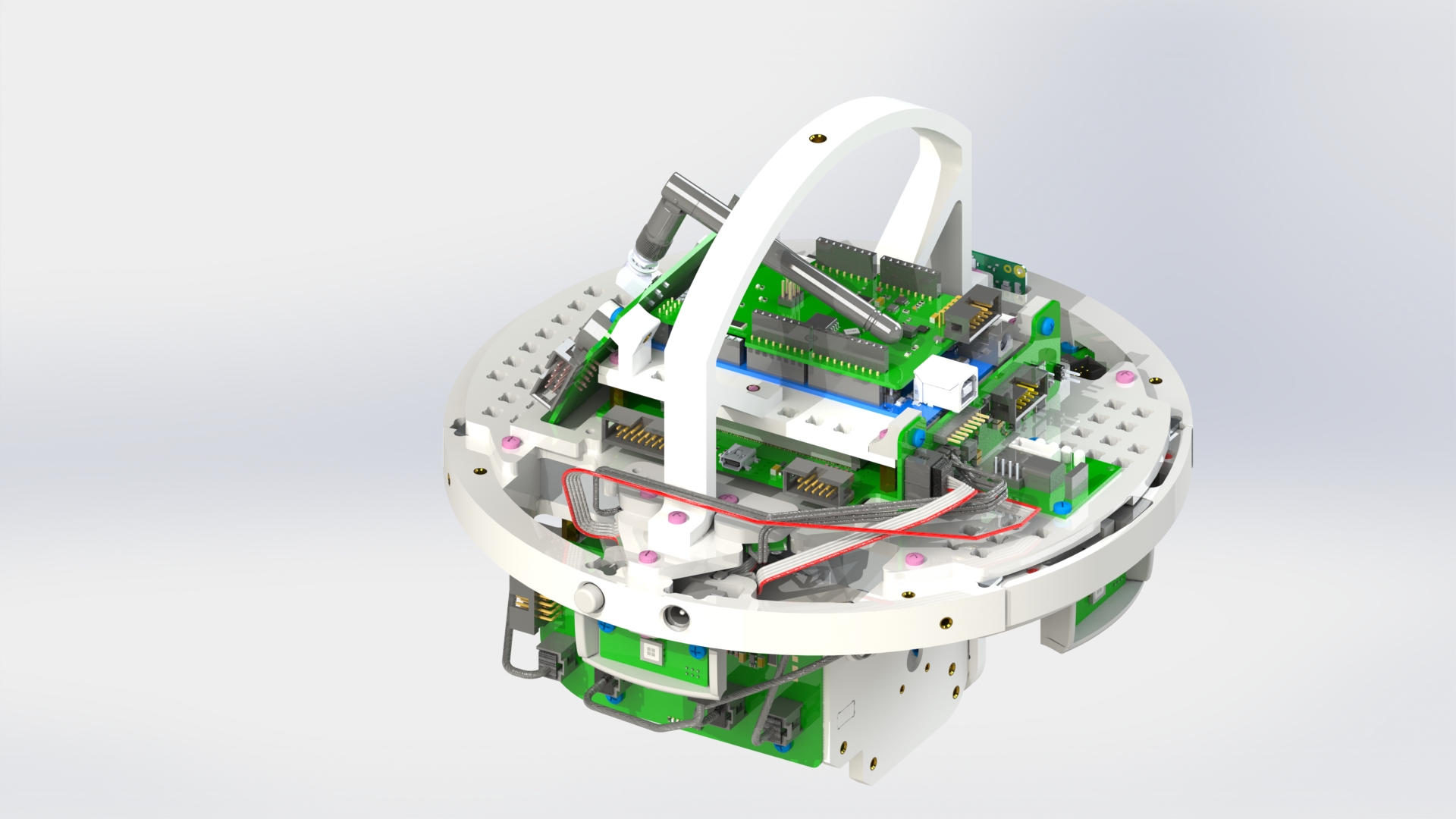
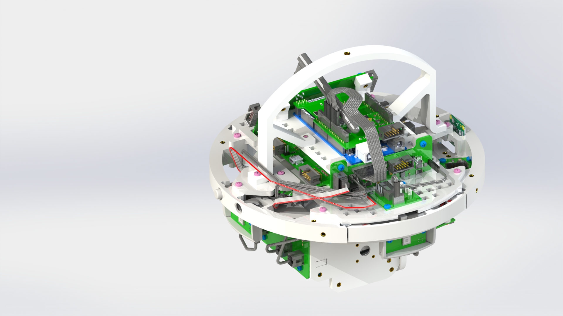
Connect the power supply system boards, reaction wheel block and solar sensors with cables (picture 5).
Picture 5.
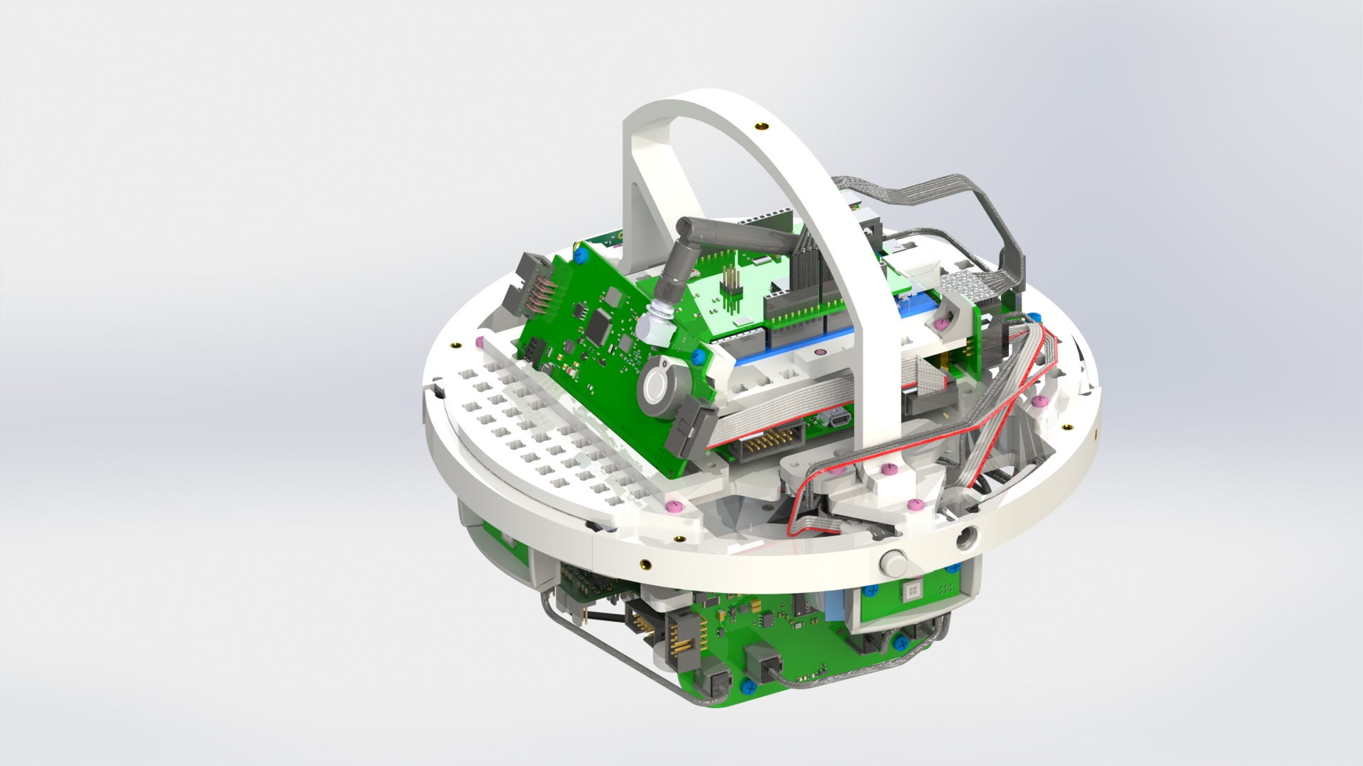
Connect the cables from the stepper motor to the stepper motor driver board (picture 6).

Picture 6.
Connect the cables of the solar panels to the solar panel board on the top (picture 7).
Picture 7.
Connect the payload shield with the solar panel board (picture 8).
Picture 8.
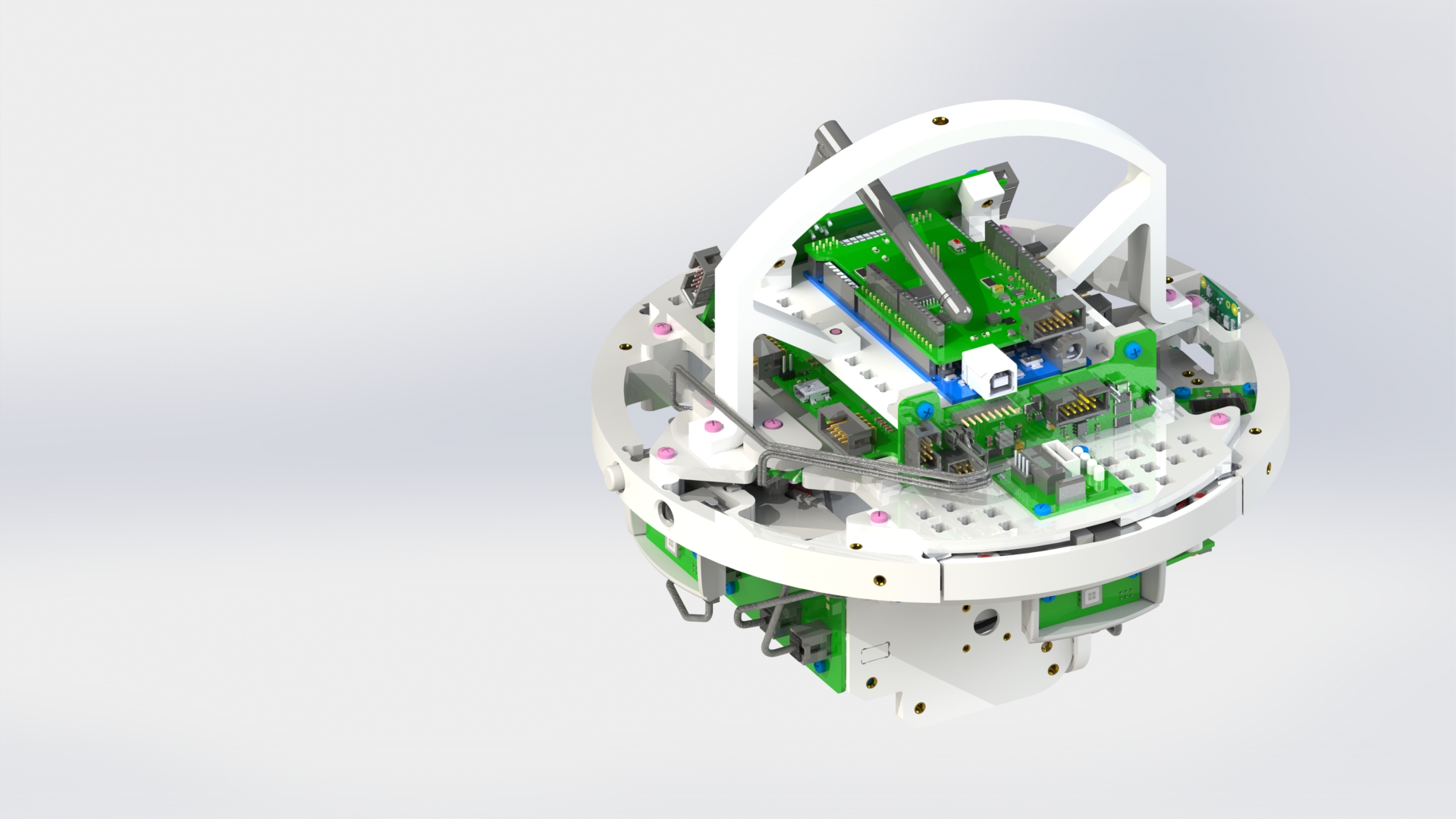
Connect the HF cable to the board of the on-board computer (picture 9).
Picture 9.
On the sides of the upper and lower bases, insert four M3x10 screws, without tightening them completely until the end (picture 11).
Install the lower hemisphere by placing it on the protruding screws and turning (picture 12).
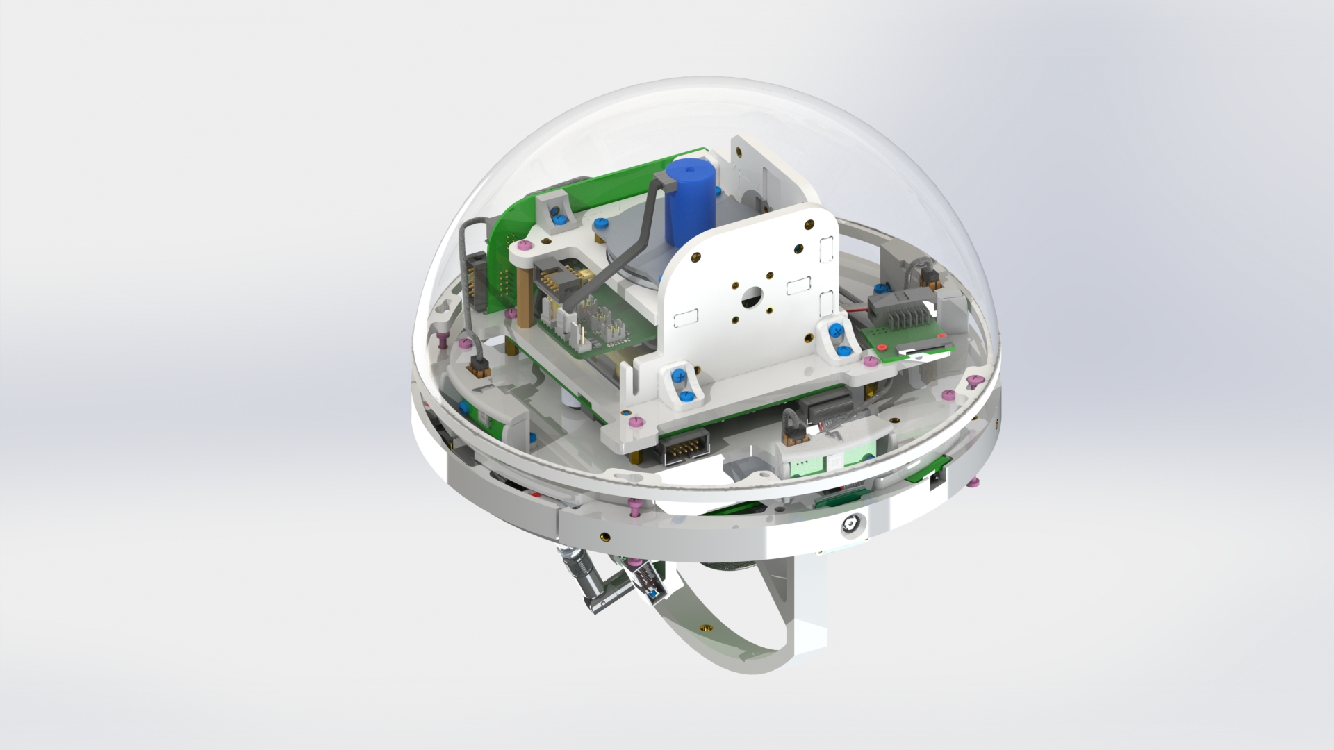

Picture 12.
Fix it with one M3x20 screw through the hole located on the back side, to the right of the camera (picture 13).
Picture 13.
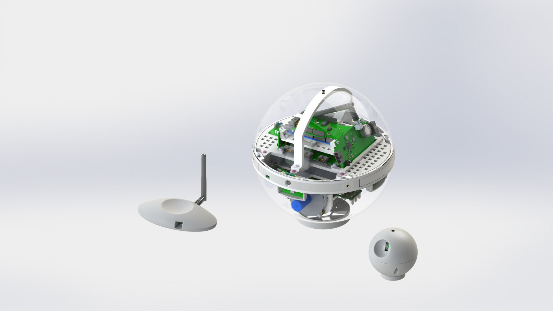
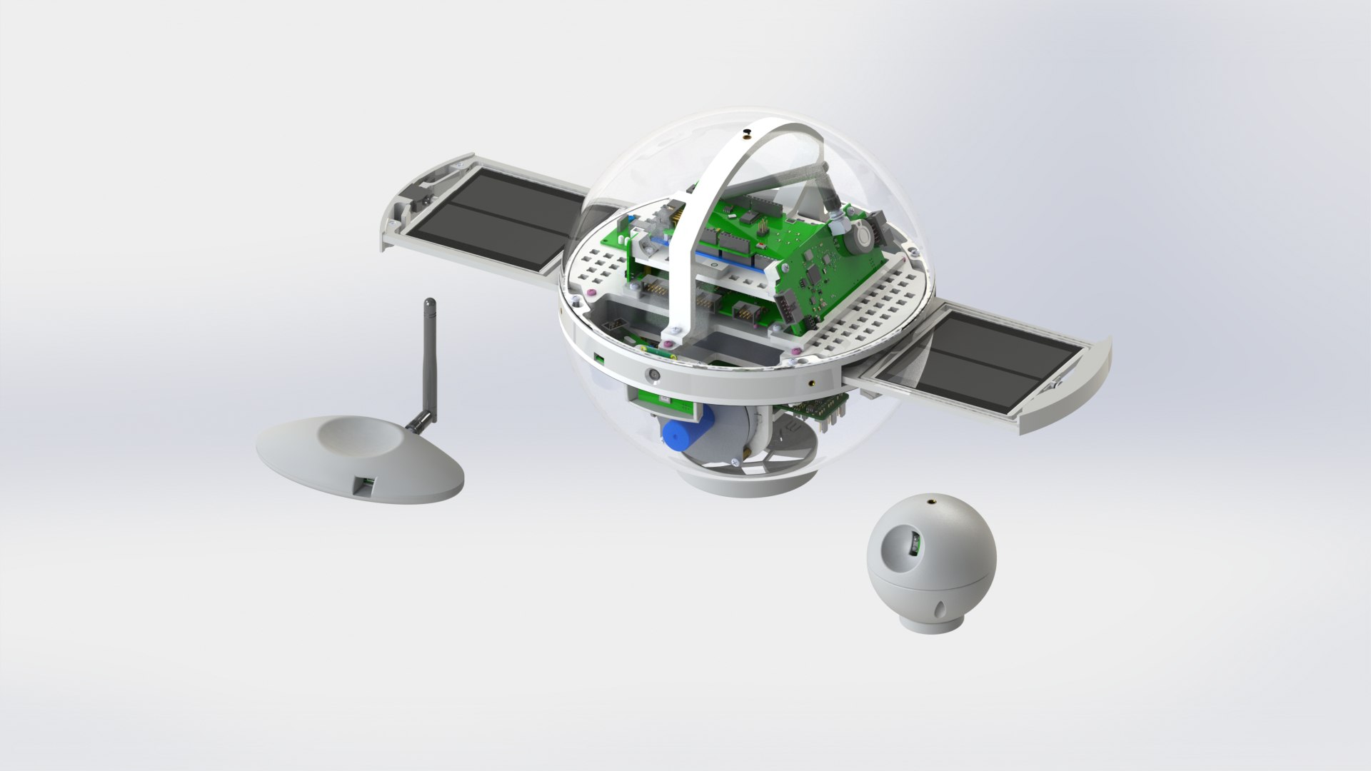
You need to calibrate the white end switch. To do this, place the structure on the stand, facing the end switches towards you, and open the solar panels. When closing the solar panels, you should hear a characteristic click.
- If you try to close the solar panels and they "disappear" too deeply into the housing, move the end switch away from you.
- If the click occurs before the panels are aligned with the housing when closing the solar panels, move the end switch towards you.
Once the panels are aligned with the housing and the click occurs precisely at that moment, tighten the screw on the end switch to secure it.
Secure the upper hemisphere by placing it on the protruding screws and turning (picture 14).

Picture 14.
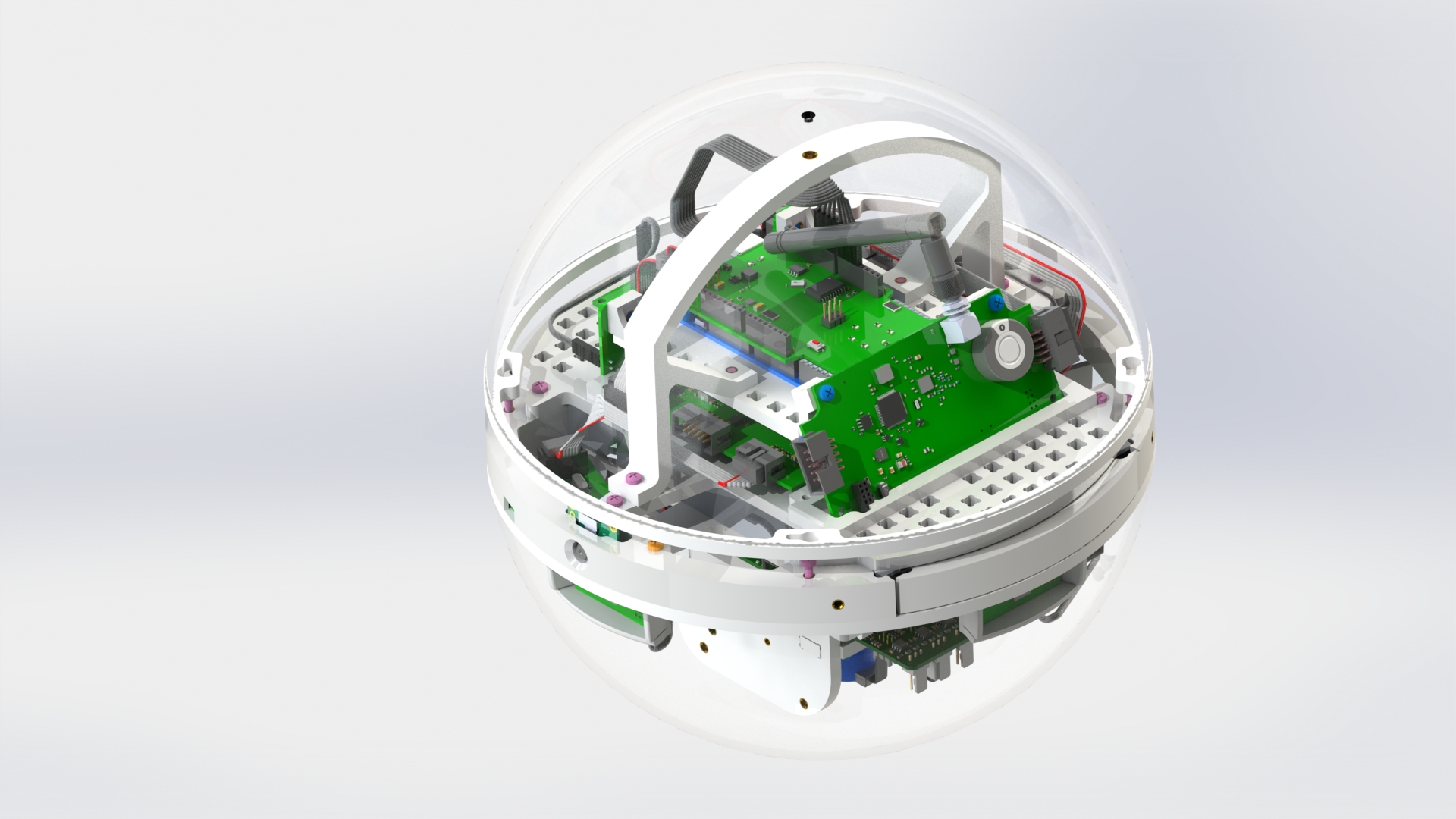
Screw the screw with ring into the hole on the upper hemisphere (picture 15).
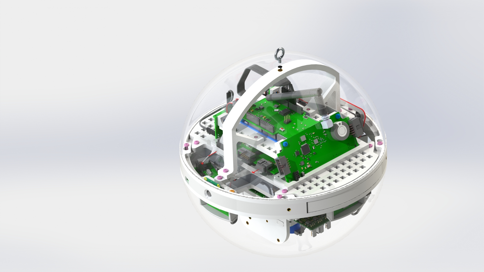

Picture 15.
The assembled Orbix (three-axis configuration) looks like this: (picture 16):
Picture 16.