Assembly of the middle part
To assemble this part of the constructor, you need to use parts from the fourth lodgments.
Components required for assembly:
- Solar sensor - 4 pcs;
- Camera board - 1 pc;
- Stepper motor - 1 pc;
- Solar panel - 2 pcs;
- Limit switch - 2 pcs;
- Stepper motor driver board - 1 pc;
- RF board - 1 pc;
- Screws M2x4 - 2 pcs;
- Screws M2x8 - 4 pcs;
- Screws M3x6 - 22 pcs;
- Screws M3x10 - 22 pcs;
- Brass stand PCHSN-12 - 4 pcs.
Assembly order
Assembly of solar sensors
- Connect solar sensor board #1 to the housing marked with the number 1 using two M3x6 screws (picture 1).
Note that the solar sensor board should be inserted into the housing from bottom to top, aligning the connector with the cutout on the housing.


Picture 1.
Connect the boards of the remaining solar sensors to their respective housings using two M3x6 screws for each sensor (pictures 2-4).
Picture 2.


Picture 3.

Picture 4.
Assembly of solar panels
Connect the mechanism of opening the lower solar panel to the side using two M2x10 screws (picture 5).

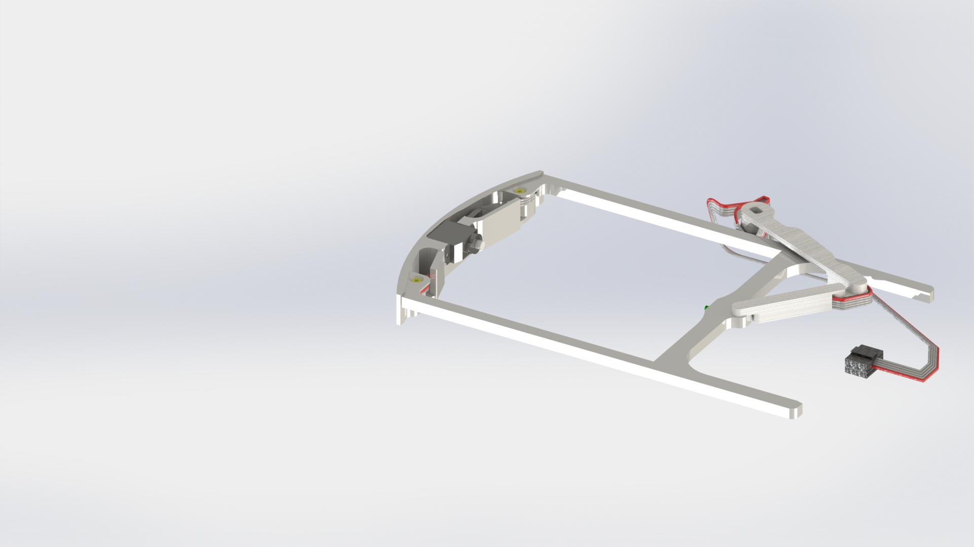
Рисунок 5.
Insert the panel into the frame from the inner wall to the outer side (picture 6).

Picture 6.
Connect the mechanism of opening the upper solar panel to the side using two M2x10 screws (picture 7).
Picture 7.
Insert the panel into the frame from the inner side to the outer side (picture 8).

Picture 8.
Assembly of arches
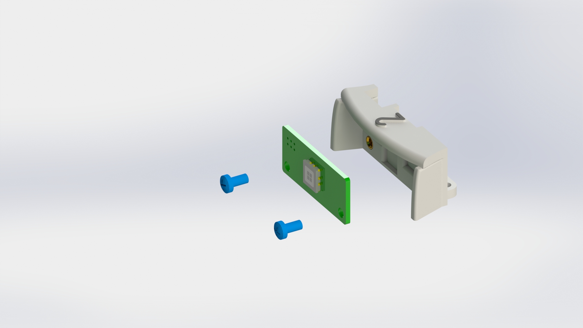
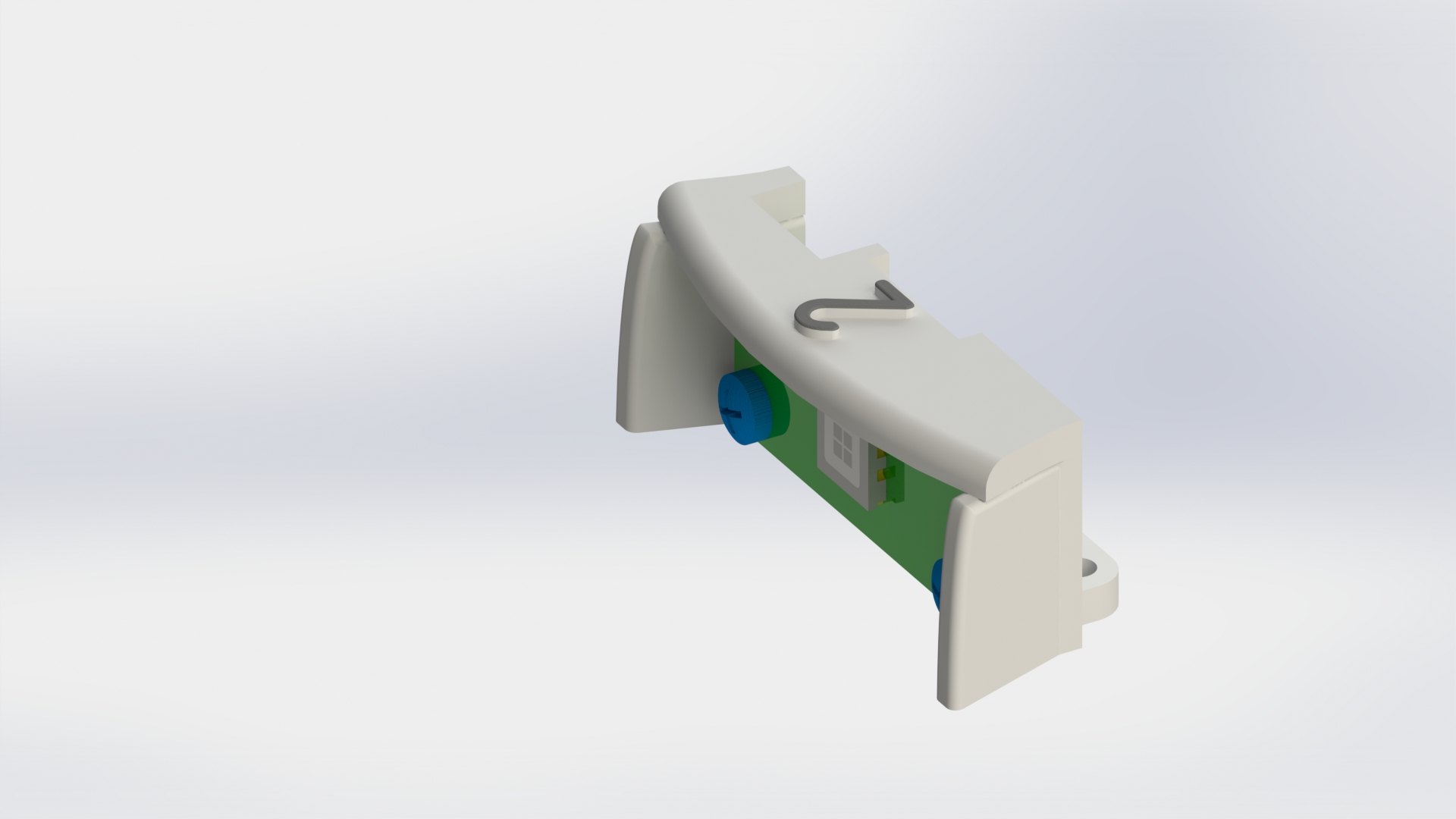
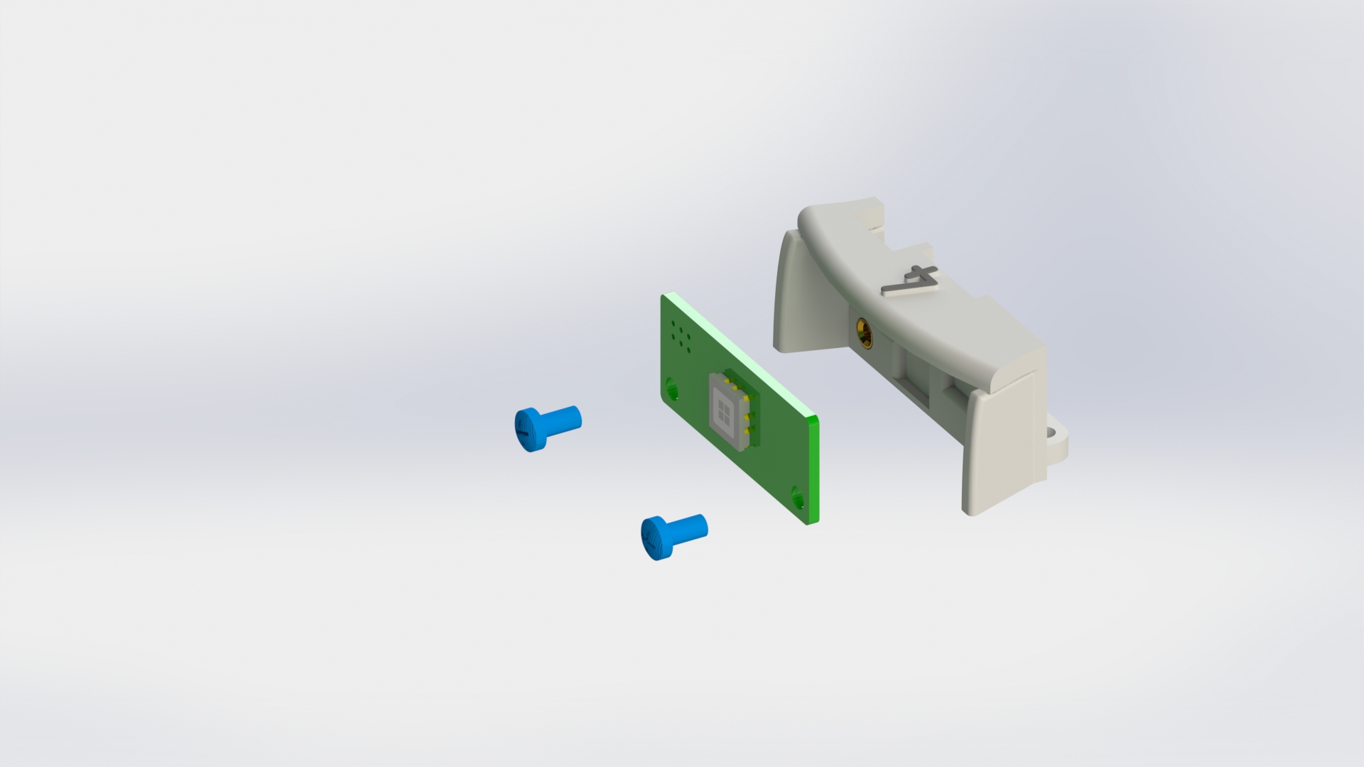
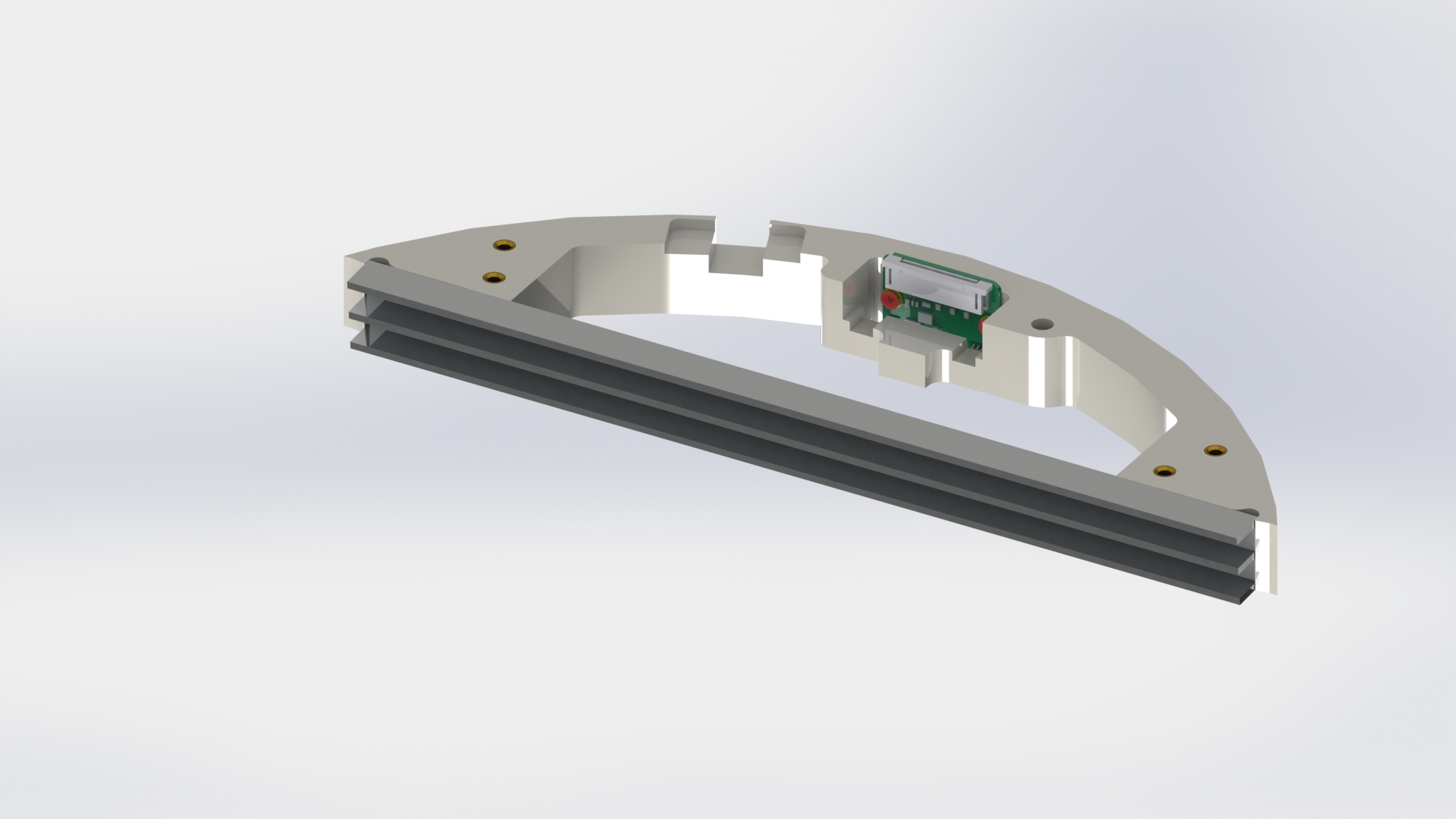
Connect the camera board to the front arch using two M2x4 screws (picture 9).


Picture 9.
Remove the tape on the side edges of the front arch and attach the guides to them (picture 10).

Picture 10.
Remove the tape on the side edges of the rear arch and attach the guides to them (picture 11).


Picture 11.
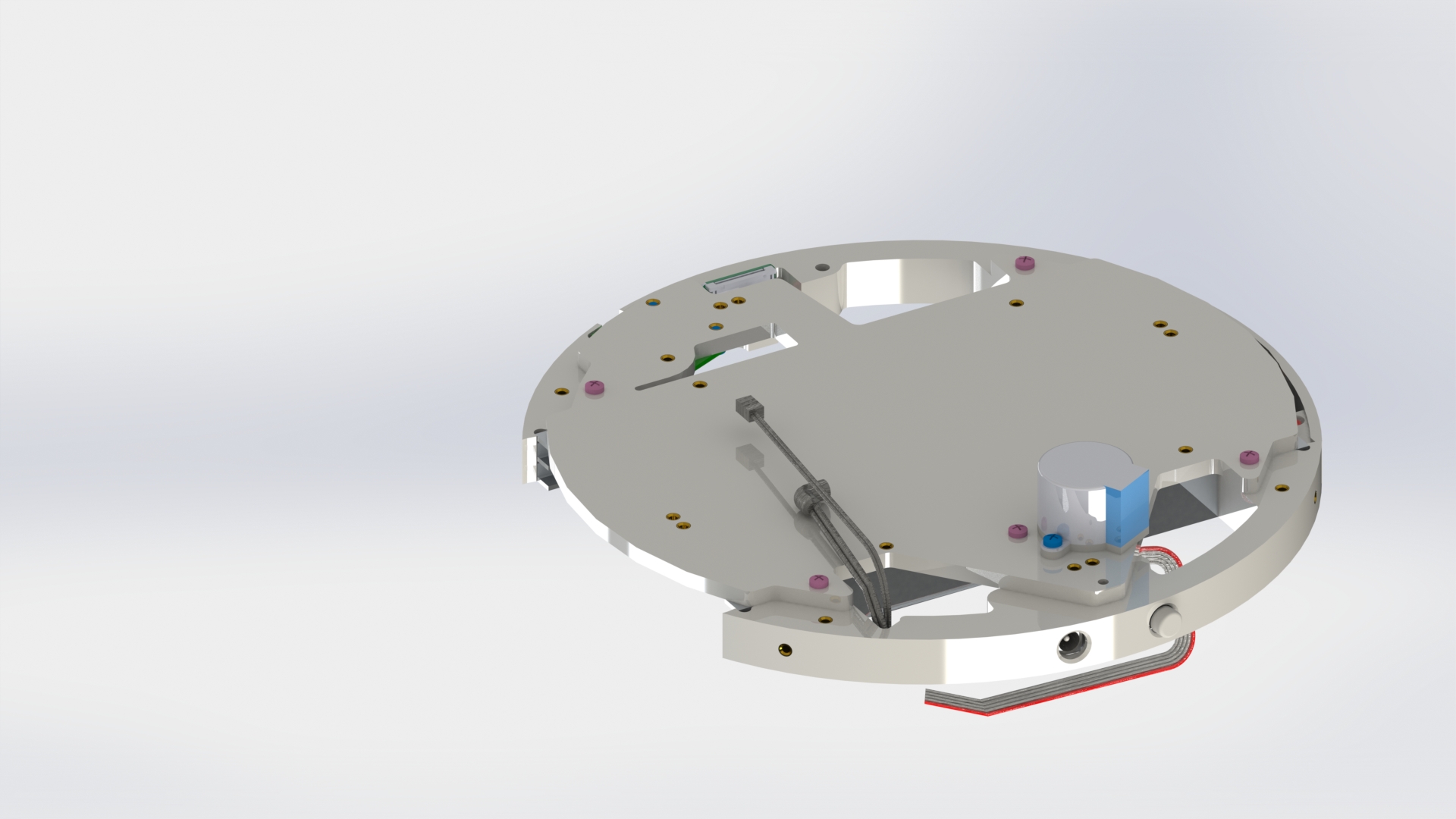
General Assembly
Attach the RF board to the bottom base with two M3x6 screws (picture 12).
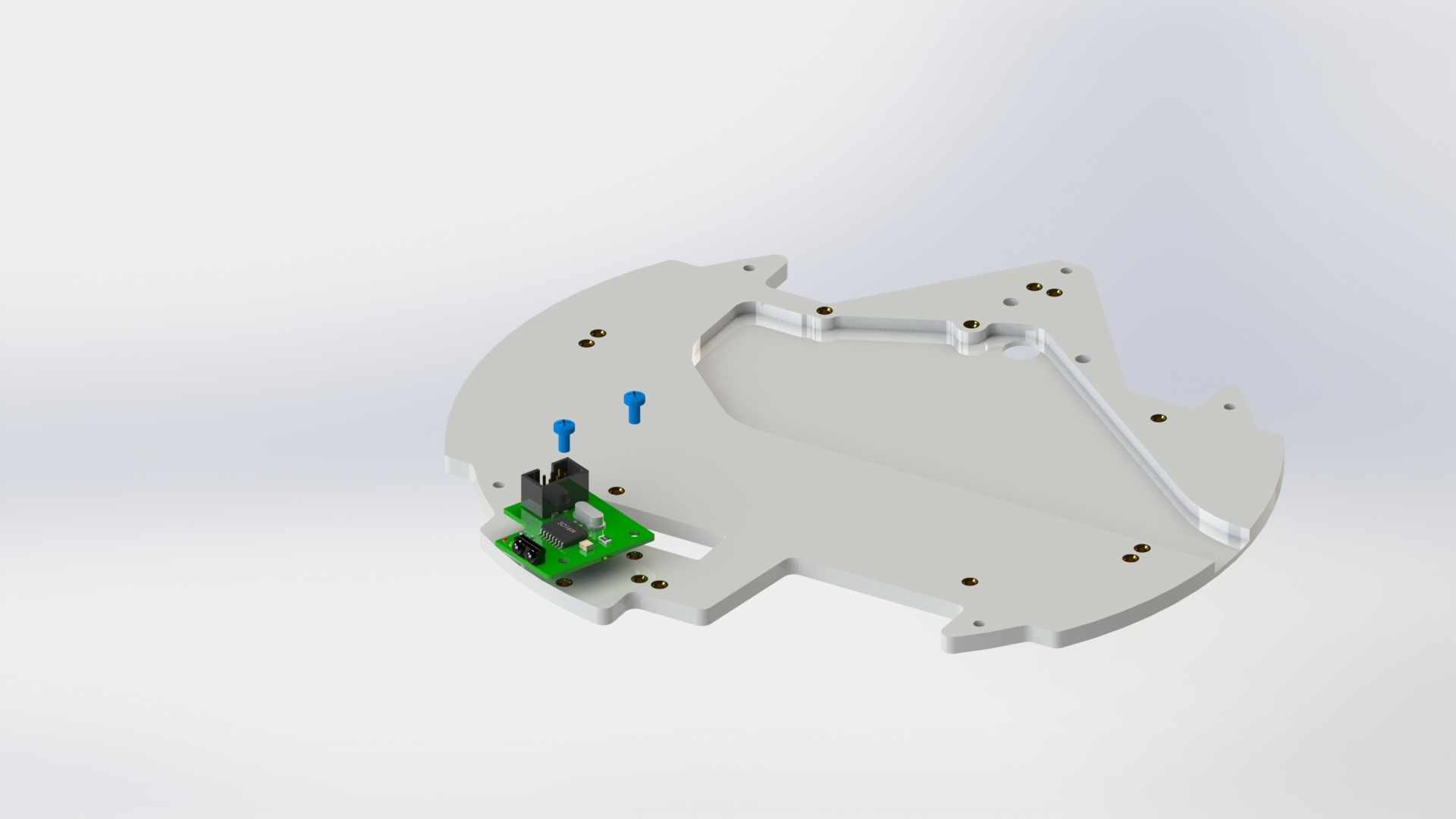

Picture 12.
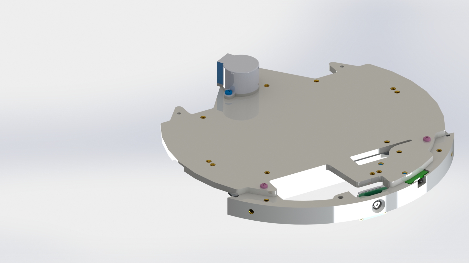
From the back side, attach the stepper motor to the housing using two M3x6 screws and a spacer (picture 13).


Picture 13.
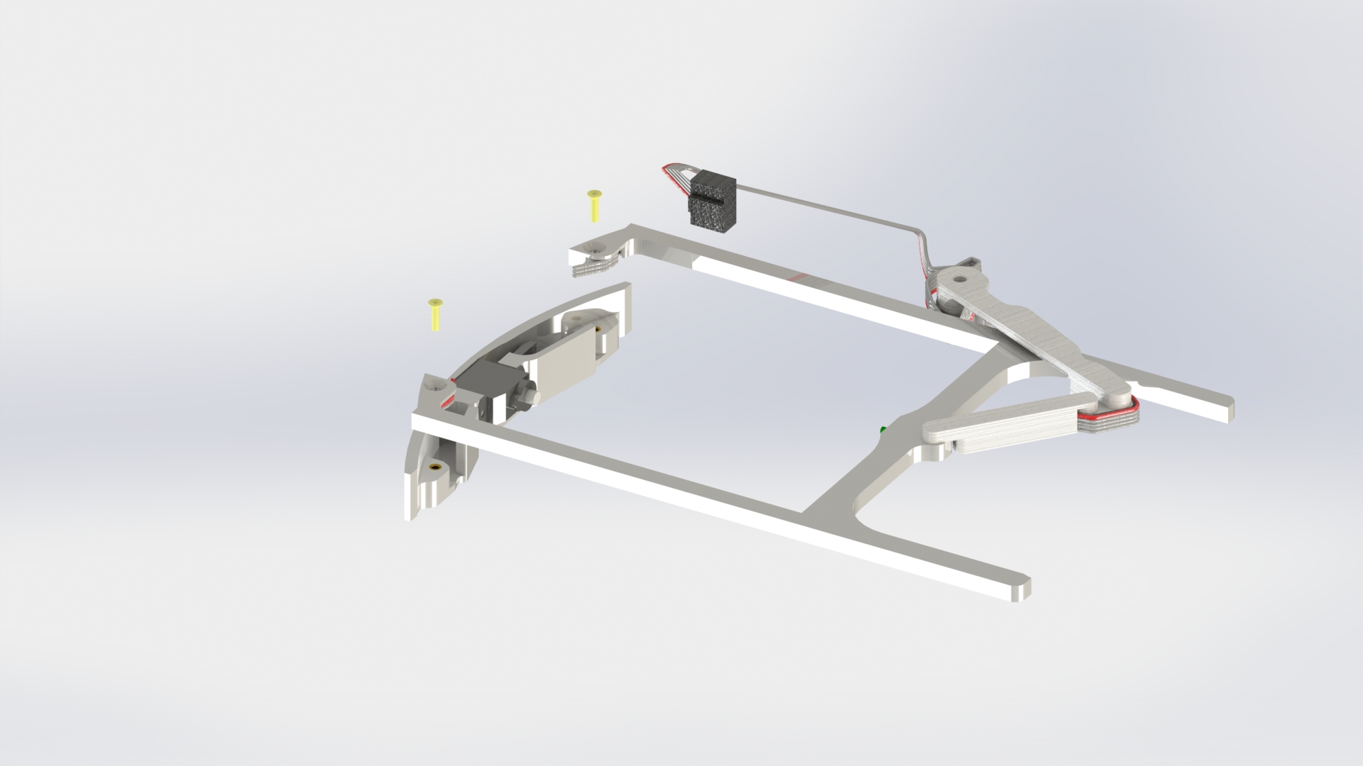
Connect the front arc to the housing using two M3x10 screws (picture 14).

Picture 14.
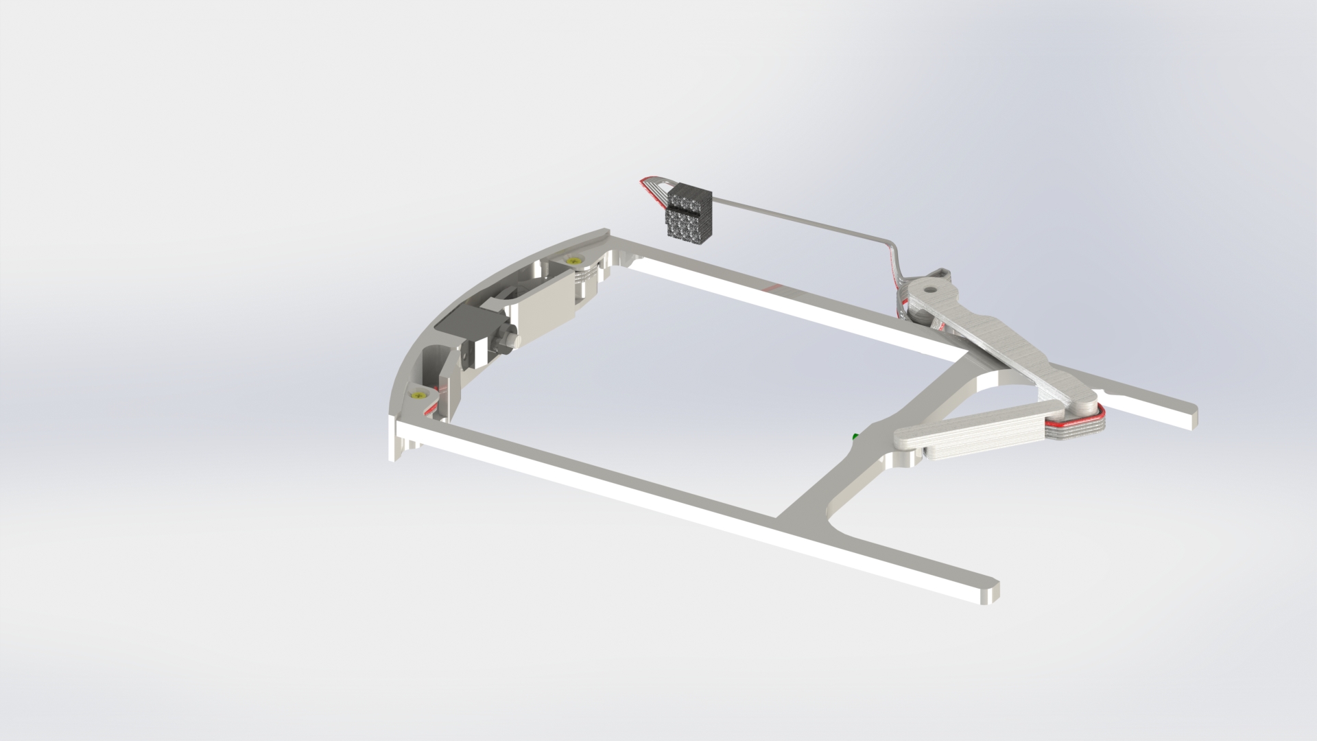
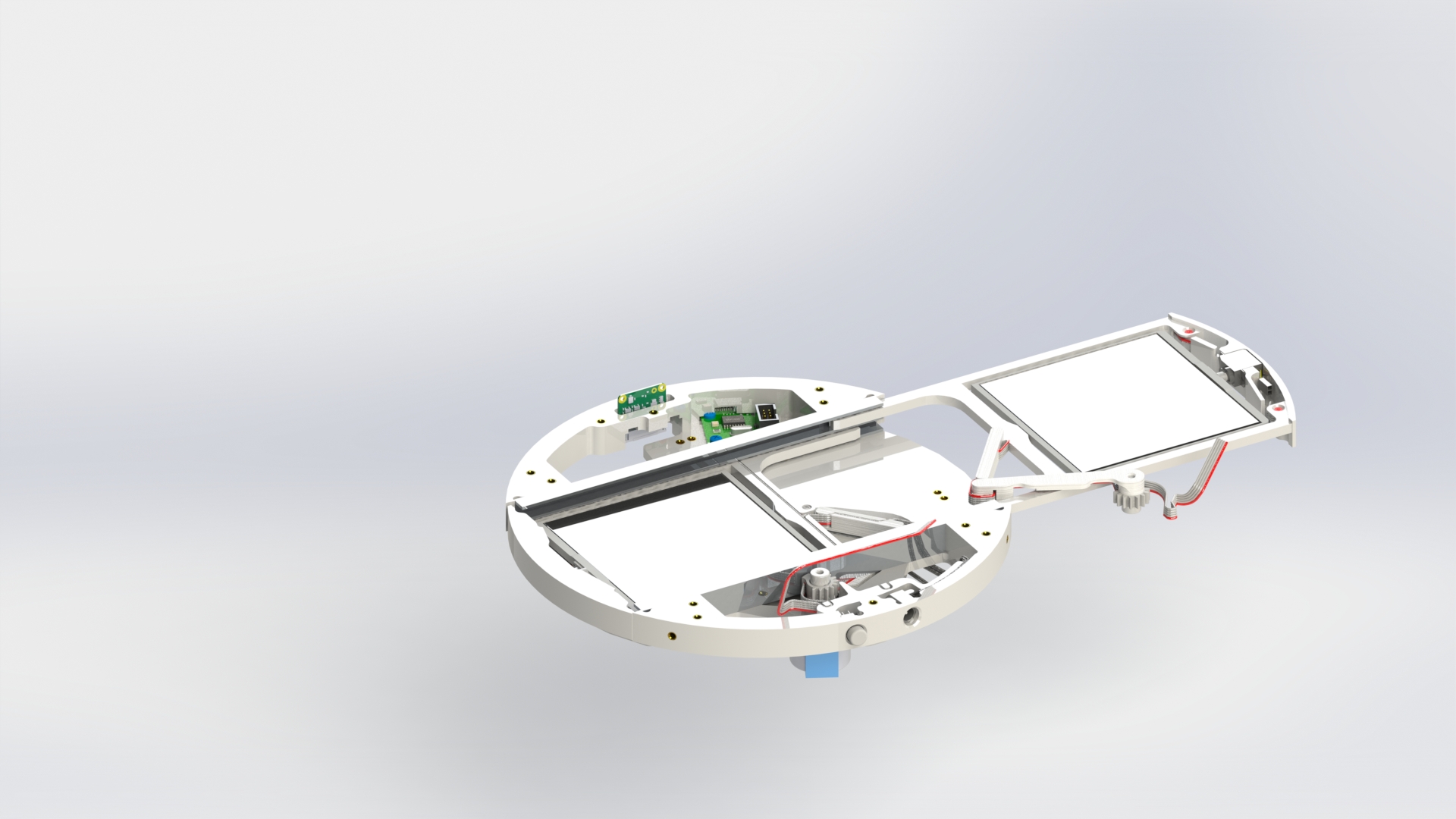
Insert the lower solar panel into the lower guide of the front arc housing. Then connect the lower guide of the rear arc, align the gear on the shaft inside the arc (picture 15).
Picture 15.
Picture 16.
Secure the arcs with four M3x10 screws from the back side (picture 17).

Picture 17.
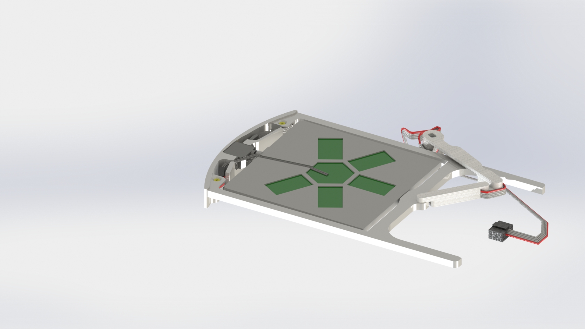
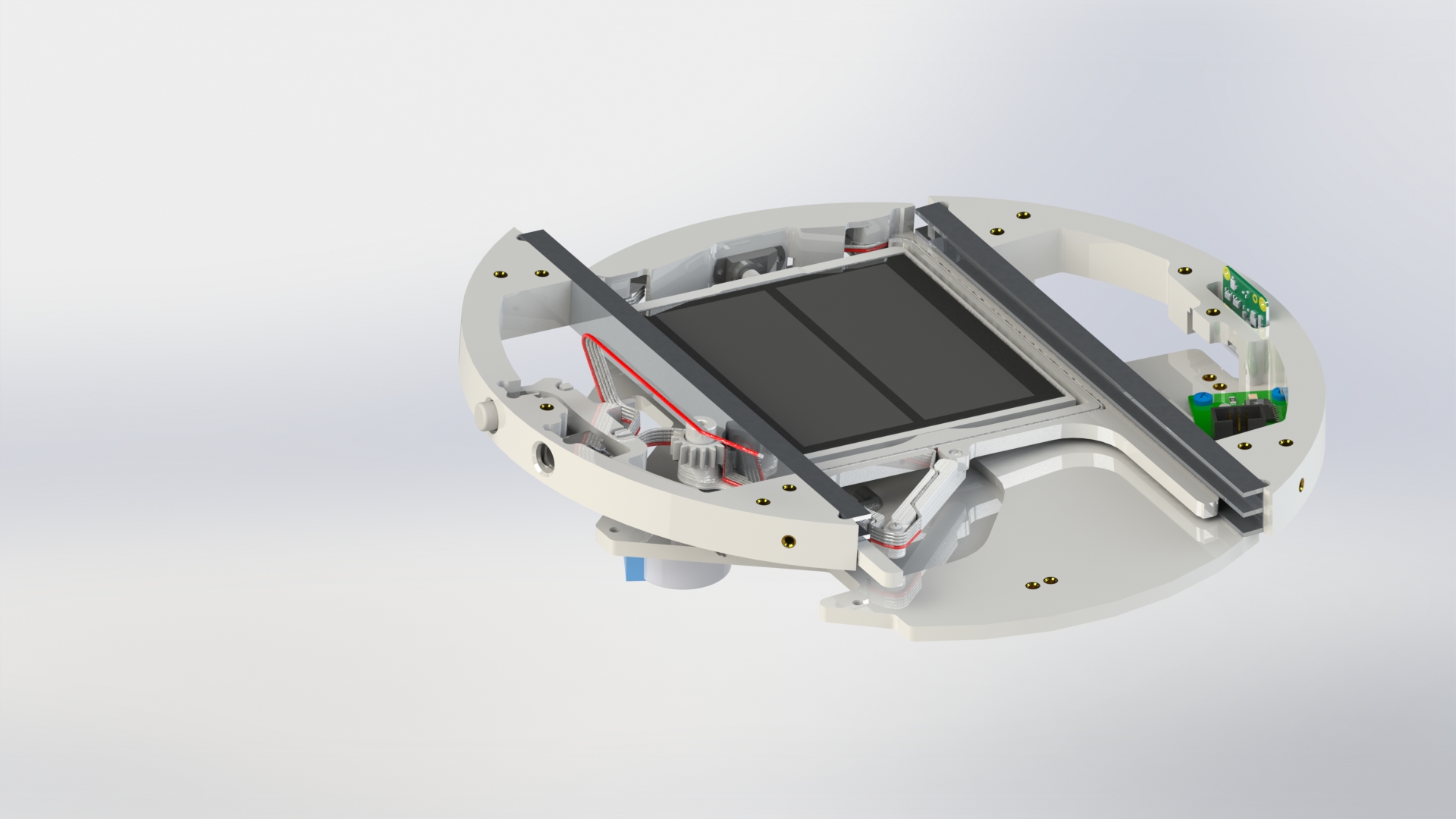
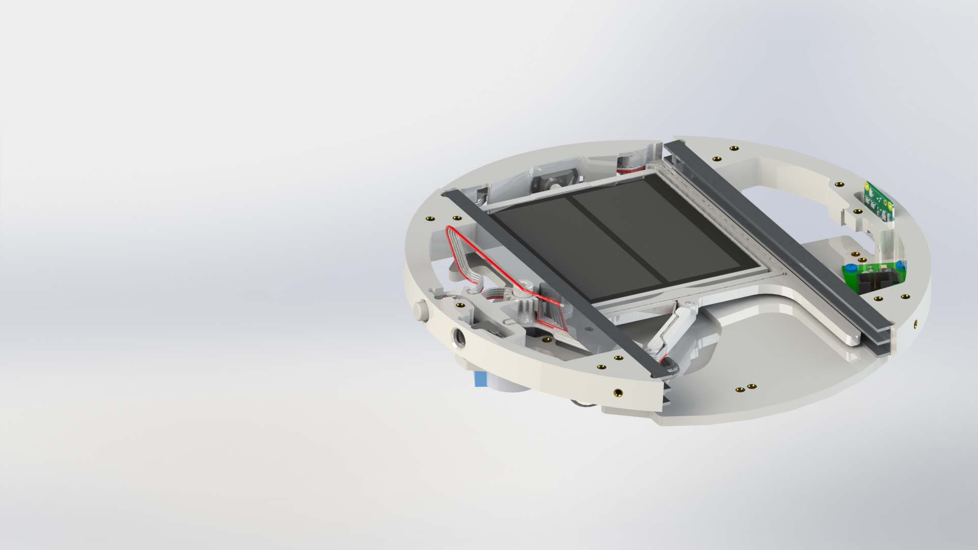
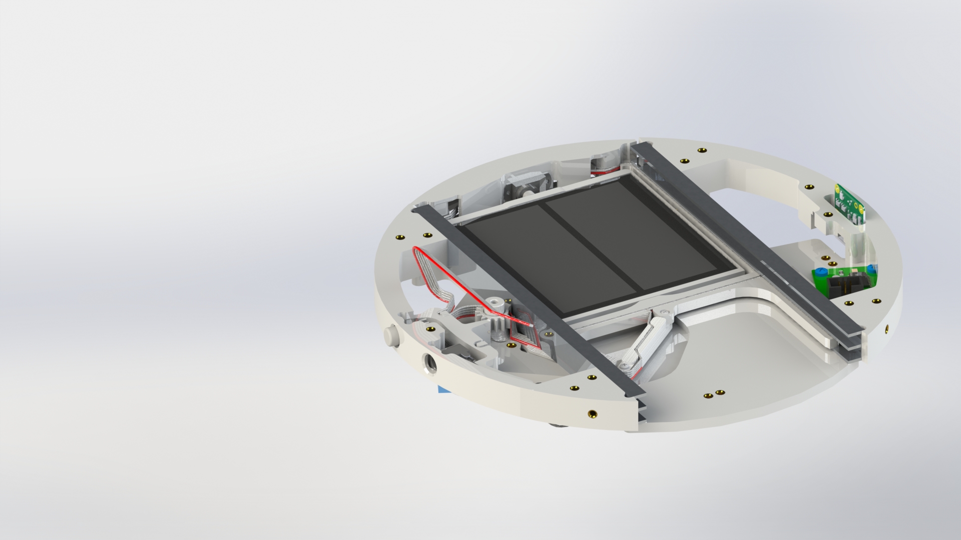
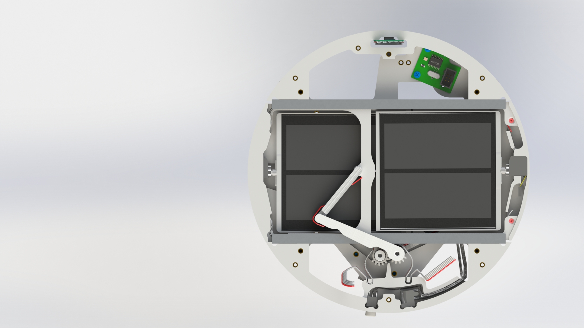
Insert the upper solar panel into the upper guides. Push it towards the center and place a gear on top of the arc. (picture 18).
Picture 18.
Secure the upper solar panel with one M3x10 screw from the back side (picture 19).

Picture 19.
Pay attention to the panel wires at the stepper motor attachment point. They should go into the specially provided slots. Они должны заходить в специально отведенные для них прорези (picture 20).
Picture 20.
Use four M2x8 screws to attach the limit switches to the housing elements (picture 21).
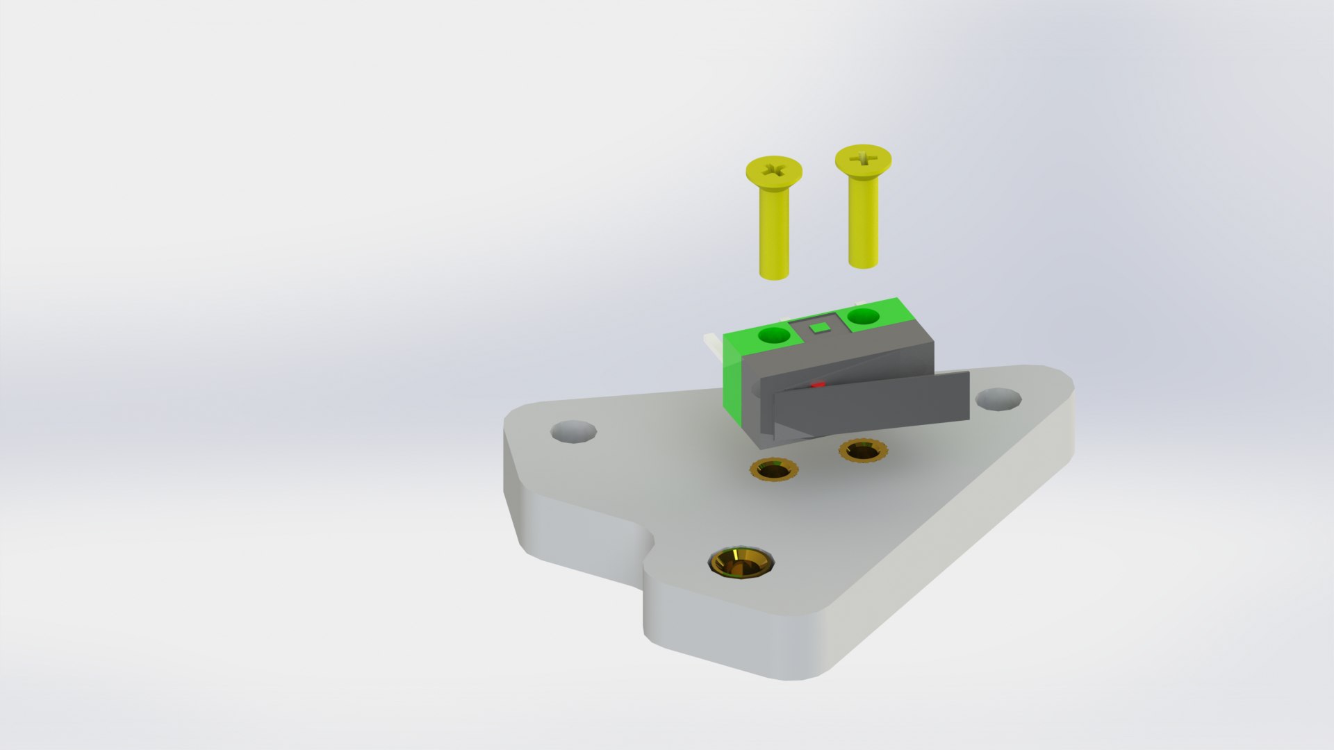
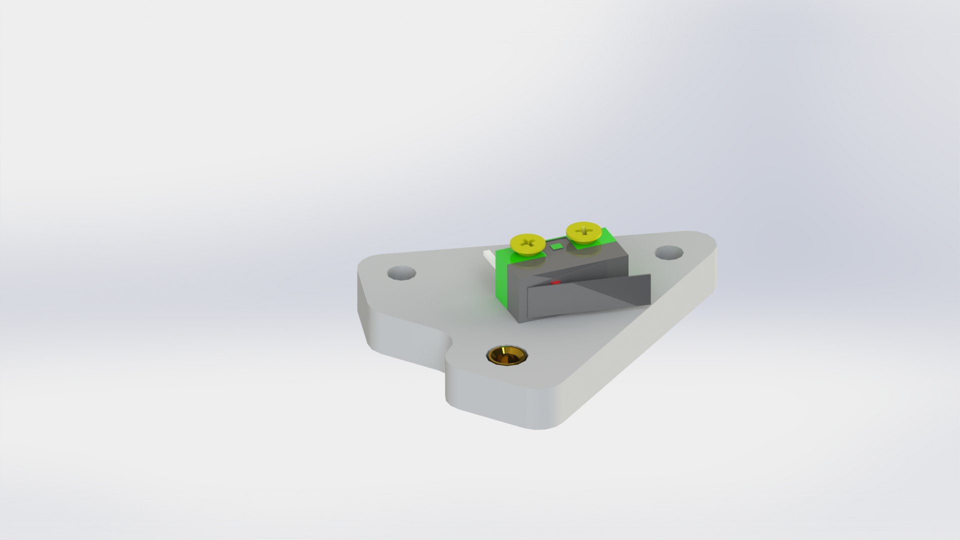
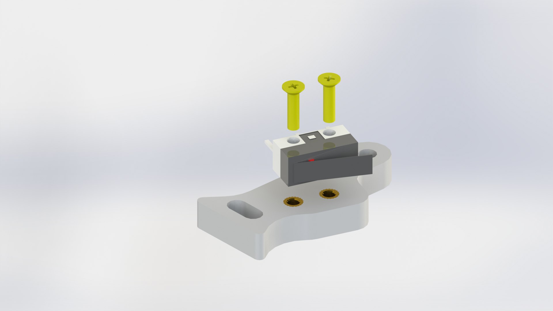
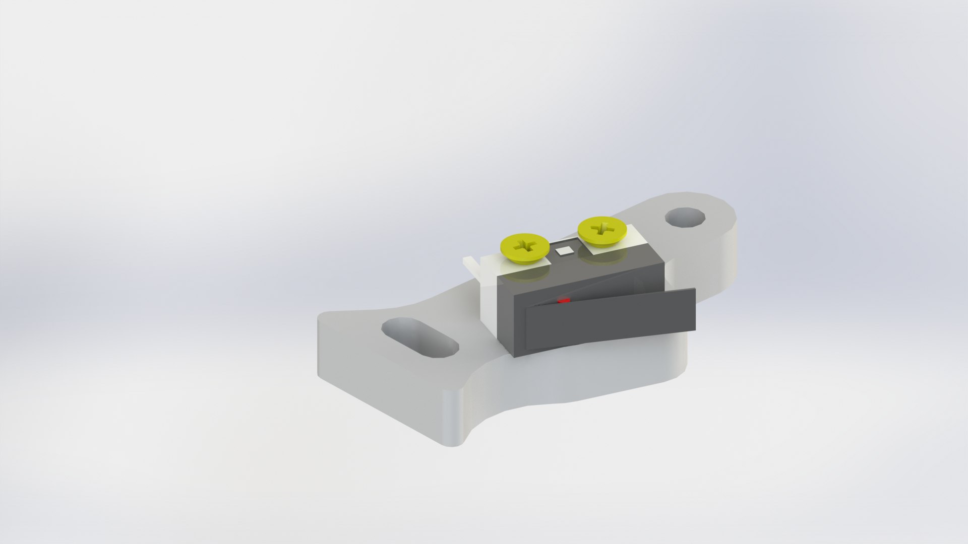
Picture 21.
Pay attention to the color of the limit switches and the markings on the housing, they should match!
Use five M3x10 screws to connect the limit switches to the main housing (picture 22).
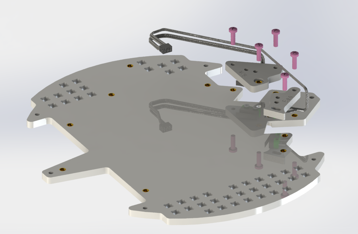
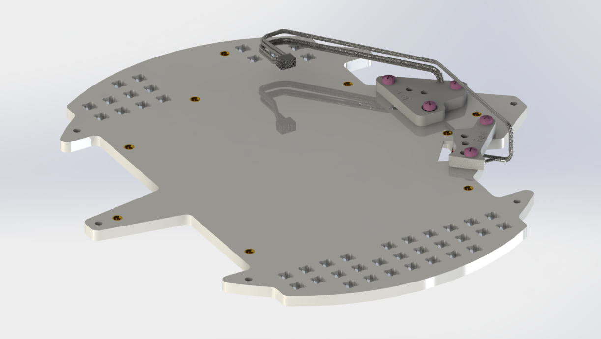
Picture 22.
Pay attention to the position of the limit switches: if you place the housing with the camera facing up, the green switch will be on the right and the white on the left!
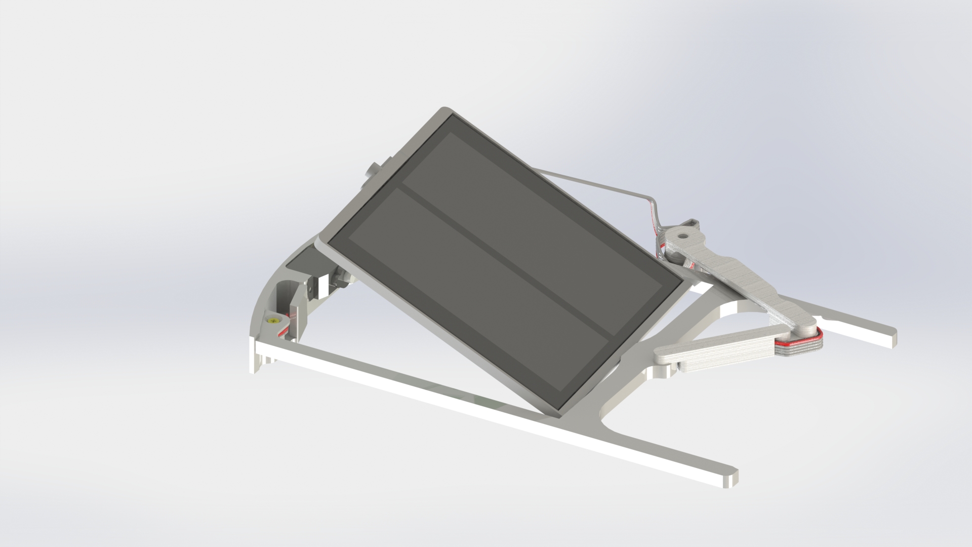
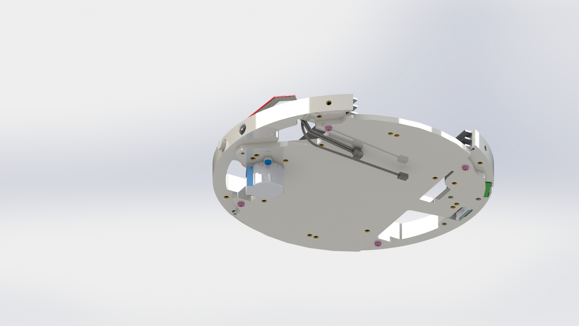
Close the solar panel housing with the cover using six M3x10 screws (picture 23).
Picture 23.
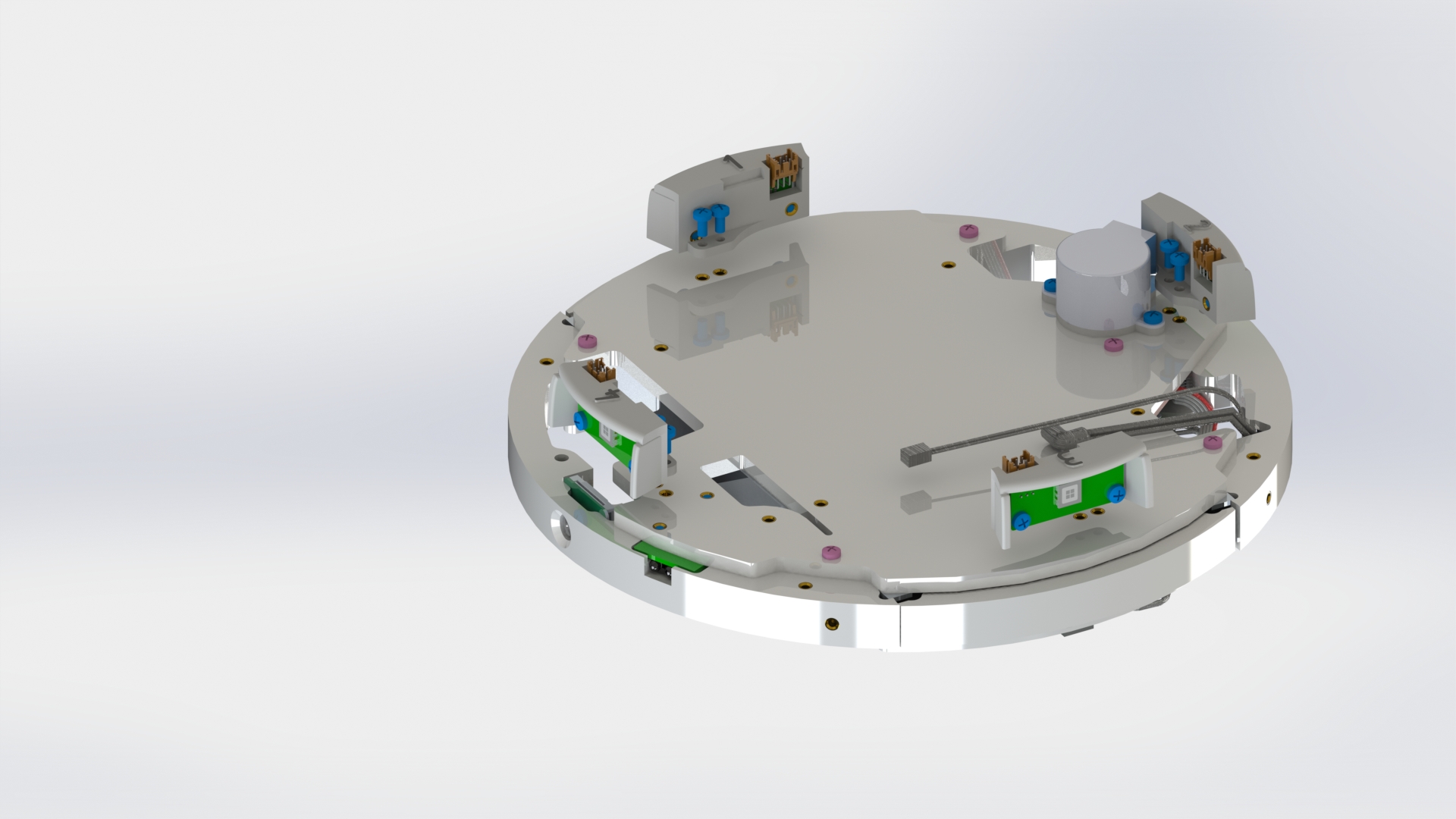
Attach the stepper motor driver board to the construction housing using two M3x6 screws (picture 24).
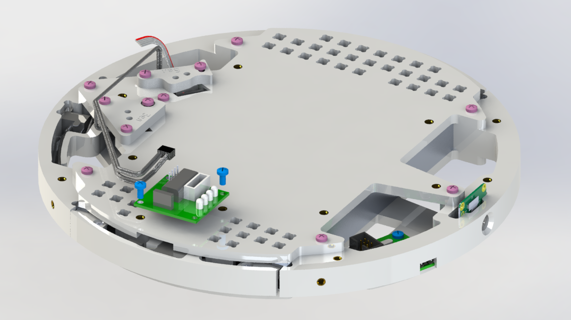
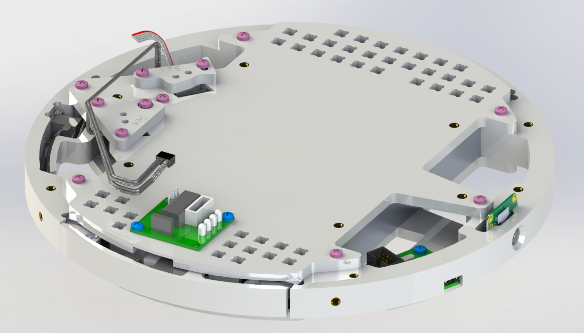
Picture 24.
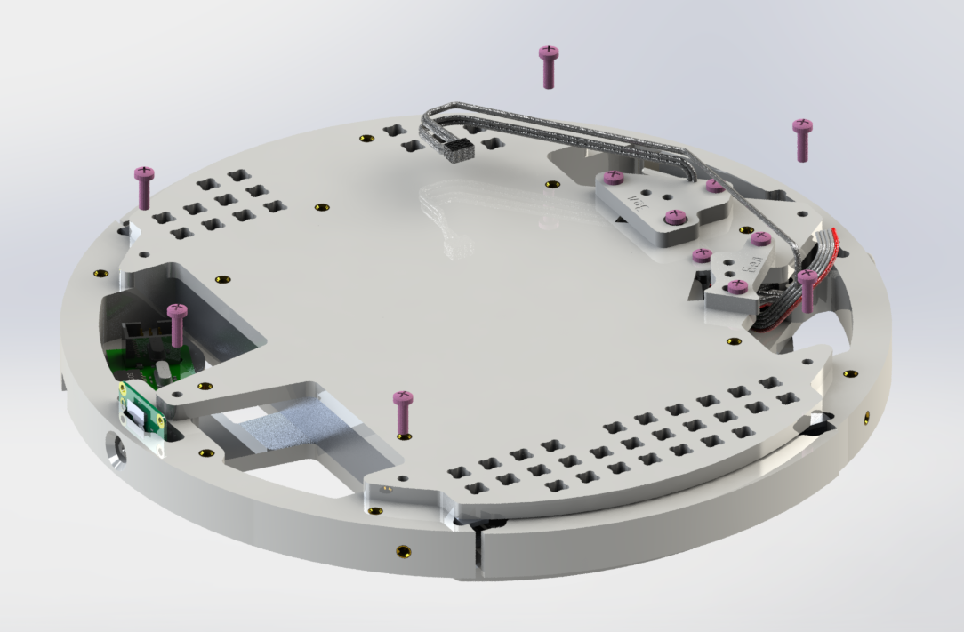
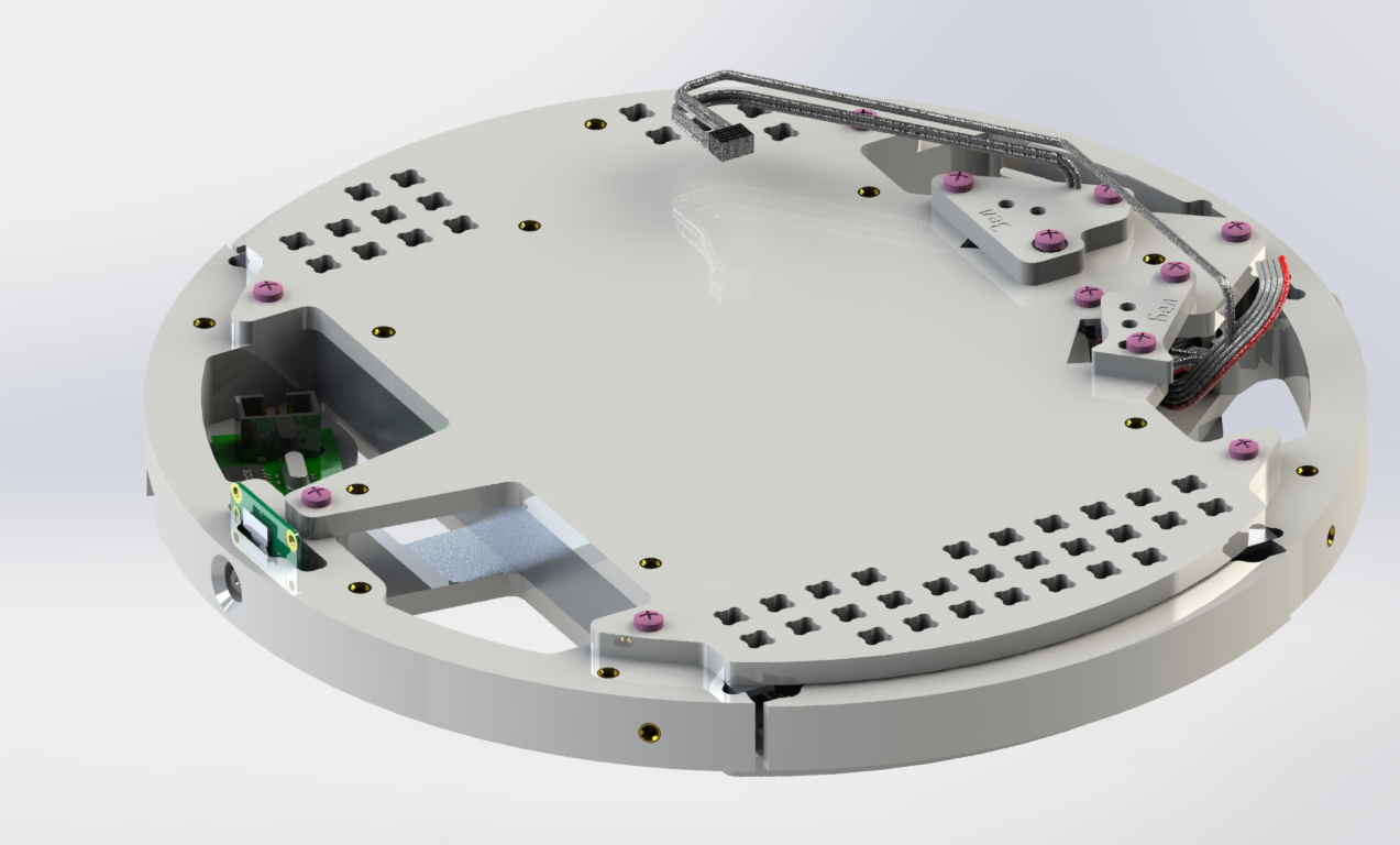
Connect the solar sensors to the construction housing with eight M3x6 screws (picture 25).
Pay attention to the numbering of the solar sensors, which goes clockwise. Solar sensor №2 is located next to the stepper motor, and sensor №4 is opposite and above the camera.
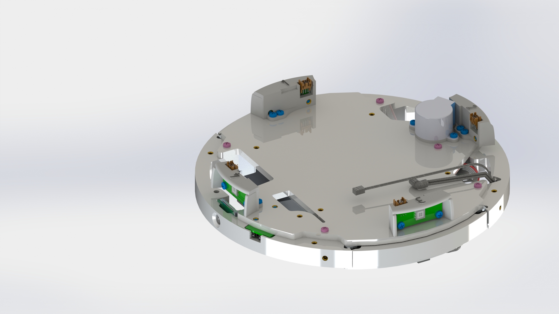
Picture 25.
Screw four brass standoffs PCHSN-12 into the housing from the side of the solar sensors (picture 26).
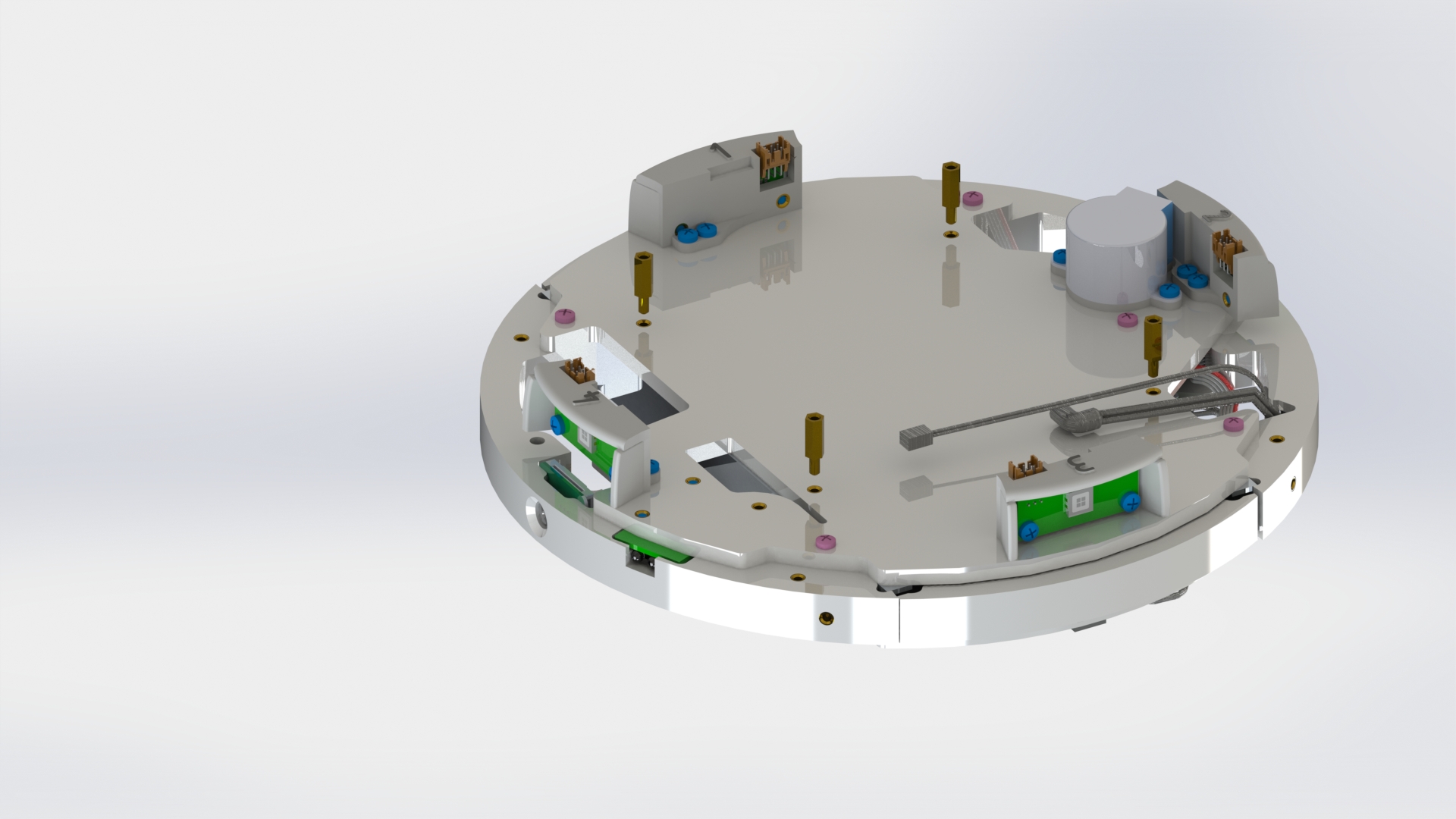
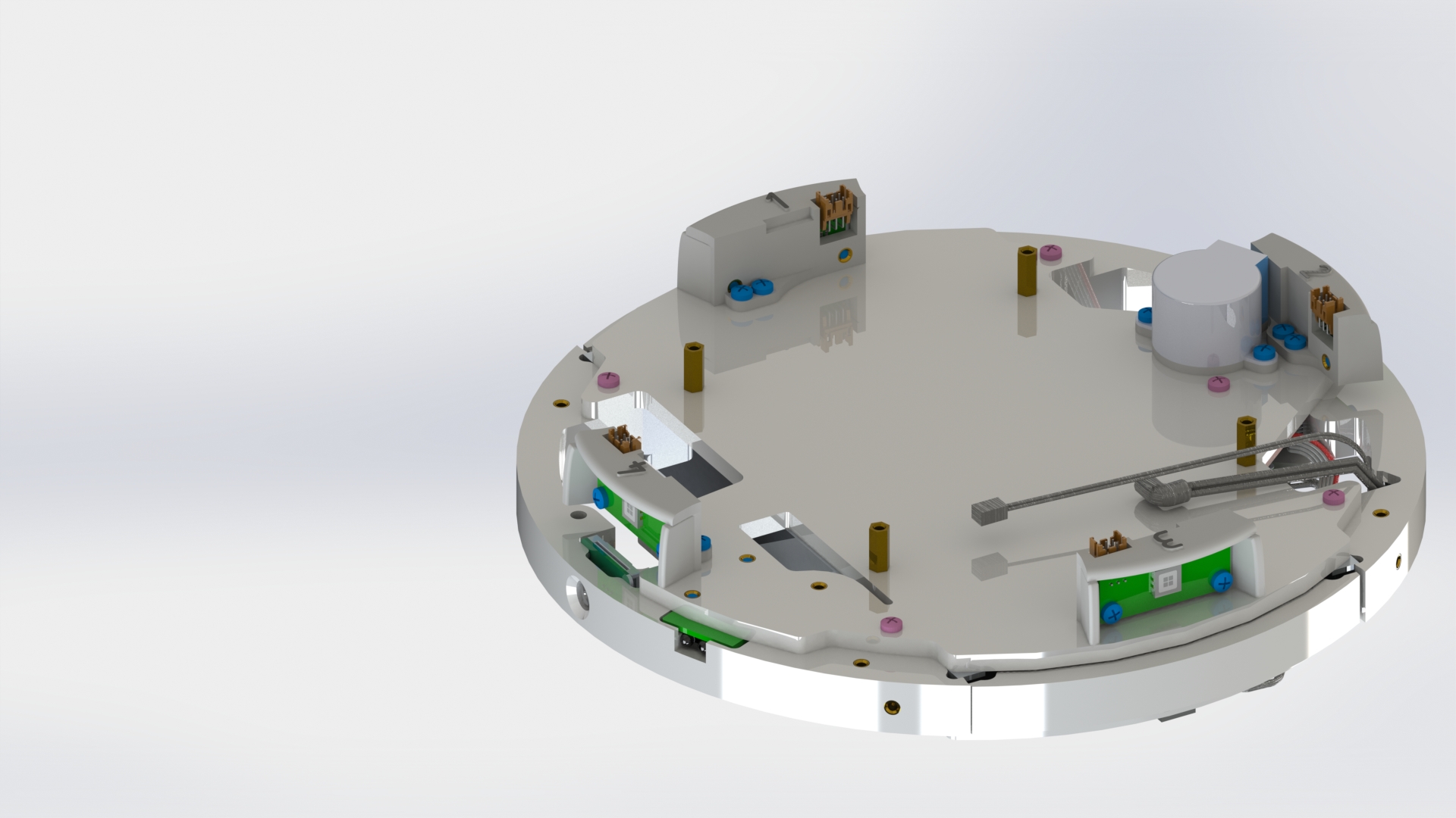
Picture 26.