Lesson 6. Getting a photo from the Meteor-M 2 satellite.
Getting to know the Meteor-M 2 satellite
Launch date of the device Meteor-M No.2 — 8 July 2014.
Purpose
Global observation of the atmosphere and the underlying surface of the Earth, which makes it possible to systematically obtain hydrometeorological and heliogeophysical information on a planetary scale.
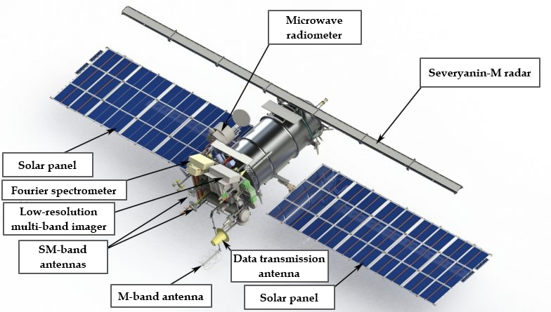
Picture 1. Meteor-M spacecraft No.2
Tasks to be solved
- Global observation of the Earth's underlying surface;
- Environmental monitoring;
- Monitoring of natural and man-made emergencies;
- solving problems of agriculture and forestry;
- Scientific research;
- collection and transmission of data from various types of PDAs (land, ice, drifting).
Main Features
- Orbit — Circular sun-synchronous, Nsr=832 km,T=101.3 min, i=98.85°;
- Power supply: average daily — up to 1000 watts, maximum for 10 minutes — up to 1350 watts;
- Active life: 7 years;
- Weight — 2700 kg;
- Payload weight — 320 kg.
Basic composition of information equipment
- Spectroscopic optical devices in the visible and IR ranges (CMSS, MSU-MR);
- Microwave radiometric equipment for temperature and humidity sensing of the atmosphere (MTVZA-GYA) — microwave radiometer;
- Infrared Fourier Spectrometer for temperature and humidity sensing (IKFS-2) — for Meteor-M spacecraft No. 2;
- Heliogeophysical Instrumentation Complex (GGAK-M), combining five devices on one platform for studying radiation of a wide energy spectrum;
- On-board radar system (BRLC), which allows you to obtain radar images of the earth's surface, regardless of weather conditions;
- A radio engineering complex for data collection and transmission, including a system for receiving data from ground-based measuring platforms (SSPS);
- The main technical characteristics of the onboard equipment of the Meteor-M spacecraft.
Low-resolution multichannel scanning device (MSU-MR):
Spectral ranges of shooting microns:
- red (0.5 - 0.7);
- Near infrared (0.7 - 1.1);
- Medium infrared (1.6 - 1.8);
- Medium infrared (3.5 - 4.1);
- Far infrared (10.5 - 11.1);
- Far infrared (11.5 - 12.5).
Capture band (when shooting from an orbit of 835 km) — 2800
Spatial resolution (pixel projection size on the Ground with H=835 km) — < 1.0 km
KMSS:
The number of spectral channels is 3 Spectral ranges of shooting, microns:
- green MSU-50 (0.37 ÷ 0.45), MSU-100 (0.535 ÷ 0.575);
- red MSU-50 (0.45 ÷ 0.51), MSU-100 (0.63 ÷ 0.68);
- near infrared MSU-50 (0.58 ÷ 0.69), MSU-100 (0.76 ÷ 0.9).
The capture band with two cameras working simultaneously is 900 km, the resolution is 60-120 m
On-board radar complex BRLK:
The carrier frequency of the probing signal is 9500-9700 MHz
The width of the shooting band is at least 600 km
Spatial resolution:
- Low resolution mode – 0.7 x 1.0 km;
- Medium resolution mode – 0.4 x 0.5 km.
Microwave scanner for temperature and humidity sensing of the atmosphere MTVZA-GYA:
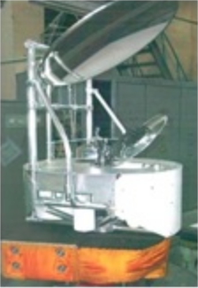
Picture 2. Microwave scanner for temperature and humidity sensing of the atmosphere
- Number of channels – 29;
- Spectral range – 10.6 - 183.31GHz;
- Field of view – 1500km;
- the resolution is 16-198 km.
The letters GY in the abbreviation were added in honor of Gennady Yakovlevich Guskov (1919-2002), an outstanding designer of space instruments, who stood at the origins of the development of a new direction in the field of microwave sensing of the Earth.
The system of data collection and transmission of SSP:
- The number of serviced PSD platforms is up to 5 thousand.
- The number of simultaneously serviced PDAs is up to 150.
Getting photos from the Meteor-M 2 satellite
The following software is used to obtain photographs from the Meteor-M 2 satellite:
- SDR# for receiving a radio signal;
- Orbitron for tracking the satellite and taking into account the Doppler effect;
- Meteor-M 2 LRPT Analyser for image decryption.
Launch SDR# and select the type of radio receiver: RTL-SDR connected via USB.
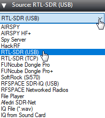
Picture 3. Choosing the type of radio receiver
In the Radio section, set the switch to WFM mode and set the bandwidth (Bandwidth) to 34000.
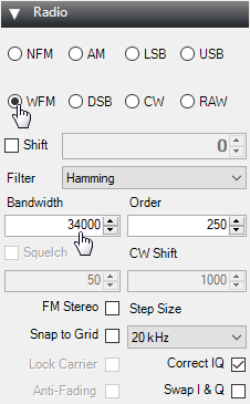
Picture 4. Switching to the WFM mode
Make sure that the "Filter Audio" checkbox is unchecked.

Picture 5. Audio Settings
Next, you need to increase the signal gain. To do this, click on the gear.

Picture 6. Signal settings
Move the slider so that the noise level increases by about 10dB.
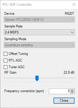
Picture 7. Increasing the signal gain
This is how the signal from the satellite Meteor-M 2 should look like.
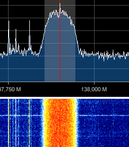
Picture 8. Signal from the Meteor-M 2 satellite
In the Tracking DDE Client section, if the Orbitron is connected correctly, information about the tracked satellite will appear.

Picture 9. Information about the tracked satellite
Launch Orbitron and update TLE first. Click on the button with the tools.

Picture 10. Launching Settings
Click on the zipper button to update TLE.
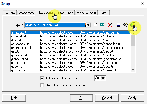
Picture 11. Orbitron Software Settings
Then select the file with information about weather satellites. Click on the Load TLE button.
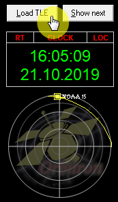
Picture 12. A file with information about weather satellites
Download the list weather.txt
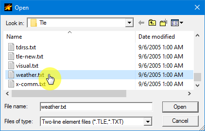
Picture 13. The list weather.txt
Only weather satellites will appear in the side list on the right. Select Meteor-M2, NOAA15, NOAA18, NOAA19.

Picture 14. Choosing satellites
The selected satellites will be displayed in the main program window.
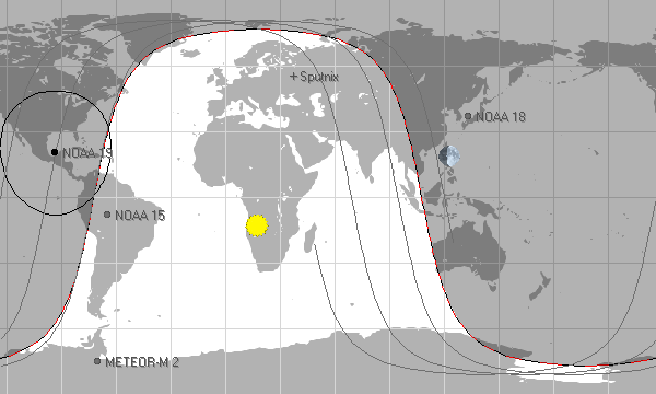
Picture 15. The main window of the program
Then go to the "Calculation" tab and click on the "Calculation" button.

Picture 16. Carrying out the calculation
The time of the satellite's flight will be calculated automatically. Go to the "Rotor" tab/Radio" and make sure the tracking button is pressed. The following correct frequency should be set in the window with the receiving frequency (Dnlink/MHz): Meteor M2 – 137.10 MHz

Picture 17. Section "Rotor/Radio"
Setting up Meteor-M 2 LRPT Analyser
To decrypt the signals received from the satellite Meteor-M 2, there is a special program Meteor-M 2 LRPT Analyzer, which receives an audio signal received from the satellite using the SDR# program. When a satellite signal is received, the Meteor-M 2 LRPT Analyzer** program starts automatically.

Picture 18. Meteor-M 2 LRPT Analizer
The signal quality can be determined by the diagram in the upper left corner of the program. Good signal quality – satellite at an altitude of 50 degrees above the horizon.
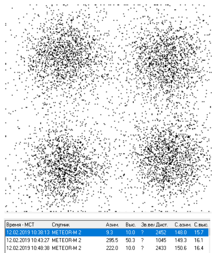
Picture 19. Good signal quality
Excellent signal quality – satellite at an altitude of 85 degrees above the horizon.
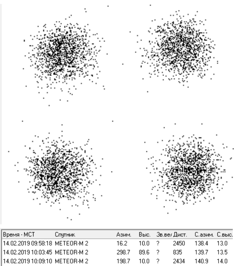
Picture 20. Excellent signal quality
Information about the signal level is displayed below the diagram.
![]()
Picture 21. Information about the signal level
In SDR# it can be seen that the signal level from the satellite is more than 20 decibels higher than the noise level.

Picture 22. Satellite signal
Images in the visible range will appear line by line on the left, and in the IR range on the right.
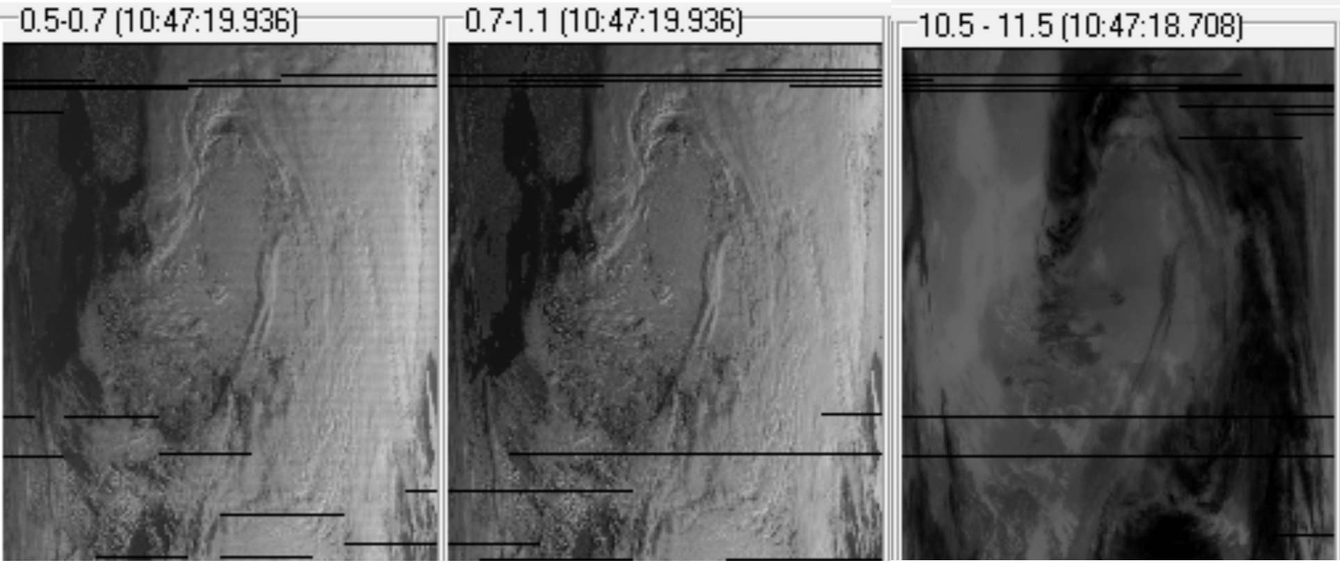
Picture 23. The image is in different ranges
When you click on the Generate RGB button, the final image will be generated.

Picture 24. Request for the final image
A special window opens with the resulting image, which can be saved.

Picture 25. The resulting image
Task:
- Analyze the resulting image and try to find cities and geographical objects on it yourself;
- Compare the picture with the one you received earlier and see how the situation in the atmosphere has changed.