Analog outputs. Potentiometer
Analog outputs
Analog In — the ports receiving the analog signal from the sensors work as input. These ports can also be programmed as digital inputs/outputs.
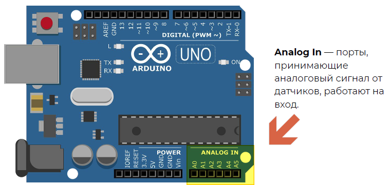
Picture 1. Analog In Ports
The analog signal can change over time, it is continuous, and the digital signal changes only in leaps (two positions 0V or 5V).
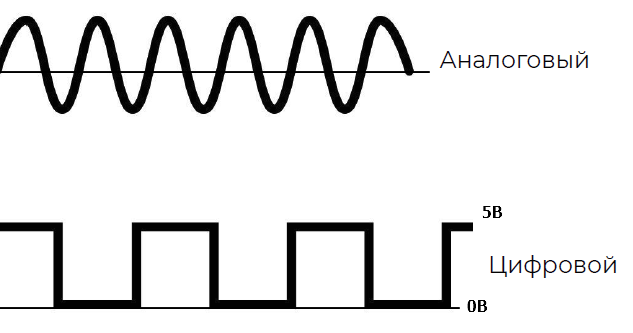
Picture 2. Analog and digital signals
The analogRead(pin) command is used to read signals from analog inputs. This command returns a value from 0, at 0V on the analog pin, to 1023 at 5V on the analog pin.
Potentiometer
A potentiometer is a variable resistor, i.e. its resistance varies depending on the position of the handle. The leftmost position corresponds to the minimum use of its internal resistance, the rightmost position corresponds to the maximum.
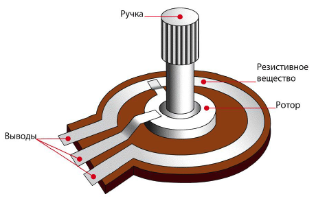
Picture 3. Potentiometer
Here it looks like a potentiometer in reality and in Tinkercad. He has 3 conclusions. The two extreme ones are +5V and GND (it doesn't matter which one is on the left and which one is on the right). The middle pin is connected to an analog pin and outputs a signal from 0 to 1023.
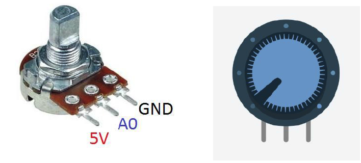
Picture 4. Potentiometer in reality and in Tinkercad
Reading the readings into the port monitor
Assembling a circuit with a potentiometer
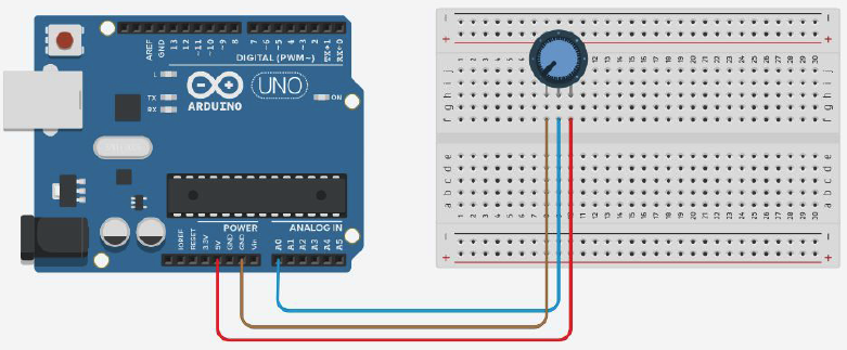
Picture 5. Circuit with a potentiometer
Program for output of potentiometer readings to the port monitor
#define potenciometr A0 //creating a variable for
the int potValue potentiometer; //creating a variable to store the potentiometer readings

void setup(){
pinMode(potenciometr, INPUT); //setting the pin to which the potentiometer is connected as an input
  Serial.begin(9600); // setting up work with the port monitor
}

void loop(){
potValue = analogRead(potenciometr); //reading the potentiometer readings and saving them to the potValue variable
  Serial.print("Potenciometr value:"); //output the phrase "Potenciometr value: "
Serial.println(potValue) to the port monitor; //output the value of the potValue variable to the port monitor and wait 100 milliseconds
  delay(100);
}
We change the brightness of the LED with a potentiometer
Assembling a circuit with a potentiometer and an LED
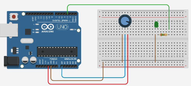
Picture 6. Circuit with potentiometer and LED
Program for changing the brightness of the LED with a potentiometer
#define potenciometr A0 //creating a variable for the potentiometer
#define led 3 //creating a variable for
the int potValue LED; //creating a variable to store the potentiometer readings

void setup(){
pinMode(potenciometr, INPUT); //setting the pin to which the potentiometer is connected as an input
  pinMode(led, OUTPUT); //setting the pin to which the LED is connected as an output
  Serial.begin(9600); //setting up work with the port monitor
}

void loop(){
  potValue = analogRead(potenciometr); //read the potentiometer readings and save them to the variable potValue
potValue = potValue/4; //divide the value of the variable by 4
  analogWrite(led, potValue); //setting the value of the potValue variable as the brightness of the LED
  Serial.print("Potenciometr value:"); //output the phrase "Potenciometr value: "
Serial.println(potValue) to the port monitor; //output the value of the potValue variable to the port monitor and wait 100 milliseconds
  delay(100);
}
Tasks
Make an analog calculator. Assemble a circuit with an Arduino board and two potentiometers connected to pins A0 and A1. Program the output to the port monitor of the values read from the potentiometers, divided by 10 and rounded. Also output the sum of these values to the port monitor.
Complicate the analog calculator. Assemble a circuit with an Arduino board, two potentiometers connected to pins A2 and A3, and a button connected to pin 5. Program the output to the port monitor of the values read from the potentiometers, divided by 10 and rounded. Also output the result of the arithmetic operation between these numbers to the port monitor. The selection of one of the four arithmetic operations must be performed using the button.