IR receiver and remote control
The purpose of the IR receiver
The IR receiver on the Arduino is capable of receiving and processing an infrared signal in the form of pulses of a given duration and frequency. The IR sensor senses the infrared signal only at a frequency of 38 kHz (sometimes 40 kHz). It is this property that allows the sensor to ignore a lot of extraneous light noise from lighting lamps and the sun. The sensor receives signals from a remote control with an IR emitter. Infrared radiation receivers are widely used in household appliances today, due to their affordable price, simplicity and ease of use. These devices allow you to control the devices using a remote control and they can be found in almost any kind of equipment.

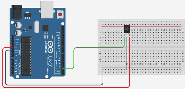
Picture 1. IR receiver
The cases of infrared receivers contain an optical filter to protect the device from external electromagnetic fields, they are made in a special shape to focus the received radiation on the photodiode. The sensor has three outputs. If you look at the sensor from the IR receiver side, then:
- on the left there will be an output to the controller;
- in the center there is a negative power supply contact (ground);
- and on the right is the positive power contact (2.7 — 5.5V).
Recognition of signals from the remote control
Assembling a circuit with an IR receiver
Picture 2. Circuit with an IR receiver
Program for recognizing signals from the remote control
#include "IRremote.h" //connecting the library
IRrecv irrecv(2); // specify the output to which the decode_results results receiver is connected
; //create a variable that stores the result
void setup() {
Serial.begin(9600); //setting up work with the port monitor
irrecv.enableIRIn(); //starting IR signal reception
}
void loop() {
if ( irrecv.decode( &results )) { //if the data has arrived
Serial.println( results.value, HEX ); //output them to the port monitor
irrecv.resume(); //accept the following command
}
}
``
## Turning on the LED from the remote control
### Assembling a circuit with an IR receiver and an LED
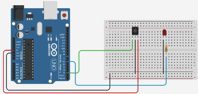
_Picture 3. Circuit with IR receiver and LED_
### Program to turn on the LED from the remote control
```cpp
#include "IRremote.h" //connecting the library
IRrecv irrecv(2); // specify the output to which the receiver
is connected decode_results results; //create a variable storing the result
int led = 6; //declare the LED
void setup() {
pinMode(led, OUTPUT); //setting the pin of the LED as the output
Serial.begin(9600); //setting up work with the port monitor
irrecv.enableIRIn(); //starting IR signal reception
}
void loop() {
if ( irrecv.decode( &results )) { //if the data has arrived
Serial.println( results.value, HEX ); //output them to the port monitor
switch ( results.value ) {
case 0xFF30CF: //if we press the "1" key, the LED turns on
digitalWrite(led, HIGH);
break;
case 0xFF6897: //if we press the "0" key, the LED turns off
digitalWrite(led, LOW);
break;
}
irrecv.resume(); //accept the following command
}
}
Control the brightness of the LED from the remote control
#include "IRremote.h" //connecting the library
IRrecv irrecv(2); // specify the output to which the receiver
is connected decode_results results; //create a variable that stores the result
int led = 6; // declare the LED
int brightness; // create a variable that sets the brightness of the LED
void setup() {
pinMode(led, OUTPUT); //setting the pin of the LED as the output
Serial.begin(9600); //setting up work with the port monitor
irrecv.enableIRIn(); //starting IR signal reception
}
void loop() {
if ( irrecv.decode( &results )) { //if the data has arrived
Serial.println( results.value, HEX ); //output them to the port monitor
analogWrite(led, brightness);
switch ( results.value ) {
case 0xFFA857: //if we press the "+" key, the brightness increases by 10
brightness = brightness + 10;
break;
case 0xFFE01F: //if we press the "-" key, the brightness decreases by 10
brightness = brightness - 10;
break;
}
irrecv.resume(); //accept the following command
}
}
``
## Transmission of IR signals between two Arduino
### Assembling a transmitter circuit with an IR LED
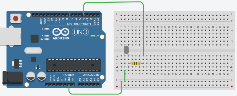
_Picture 4. Transmitter circuit with IR LED_
### Assembling a circuit with an IR receiver and an LED

_Picture 5. Circuit with IR receiver and LED_
### Programming the IR transmitter
```cpp
void setup()
{
pinMode(4, OUTPUT);
}
void loop()
{
digitalWrite(4, HIGH);
delay(1000); // Wait for 1000 millisecond(s)
digitalWrite(4, LOW);
delay(1000); // Wait for 1000 millisecond(s)
}
Programming the IR receiver
#include "IRremote.h" //connecting the library
IRrecv irrecv(2); // specify the output to which the receiver
is connected decode_results results; //create a variable storing the result
int led = 6; //declare the LED

void setup() {
pinMode(led, OUTPUT); //setting the pin of the LED as the output
  Serial.begin(9600); //setting up work with the port monitor
  irrecv.enableIRIn(); //starting IR signal reception
}

void loop() {
  if ( irrecv.decode( &results )) { //if the data has arrived
    digitalWrite(led, HIGH);
  else {
    digitalWrite(led, LOW);
  }
  irrecv.resume(); //accept the following command
}
}
``

You can read more about the switch...case [here] (http://arduino.ru/Reference/SwitchCase (http://arduino.ru/Reference/SwitchCase ) "SwitchCase").

## Task
1. Connect the servomotor to the Arduino and program the rotation control of the servomotor from the remote control.