Button
Button connection options
Let's get acquainted with the clock button. Such a button does not have a lock - this button closes the circuit only while it is pressed. Usually, these buttons have terminals connected in pairs. It is these pairs of terminals that close or open.
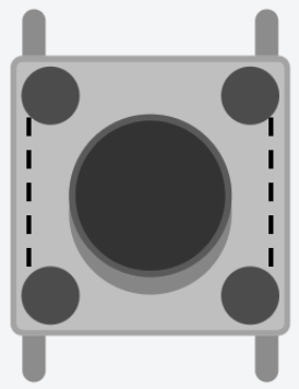
Picture 1. Button
There are 2 basic button connection schemes:
PULL UP - when the pin from which the button status information is read is connected via a resistor with a high signal level of +5V;
PULL DOWN - the pin from which information about the status of the button is read is connected via a resistor with a low signal level of 0V(GND).
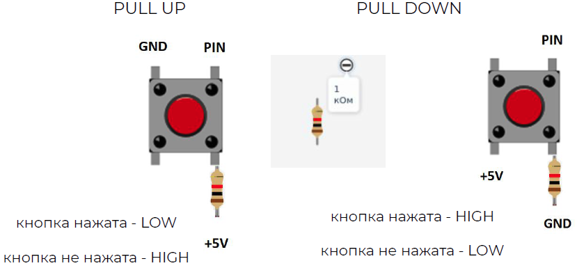
Picture 2. Two basic button connection schemes
Please note! Inside the button, the pins are connected in pairs as shown in the following figures.
PULL UP: when released, HIGH will be read from the button, and when pressed, LOW.
PULL UP when the button is NOT pressed, the pin will receive a high signal level HIGH (+5 Volts). When the button is pressed, the pin will receive a low signal level LOW(GND).
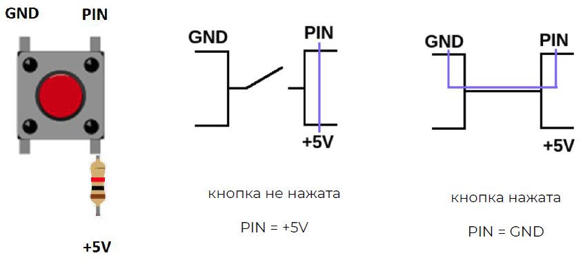
Picture 3. PULL UP scheme
PULL DOWN: when released, LOW will be read from the button, and when pressed, HIGH.
PULL DOWN when the button is NOT pressed, the pin will receive a low signal level (GND). When the button is pressed, the pin will receive a high signal level (+5 Volts).
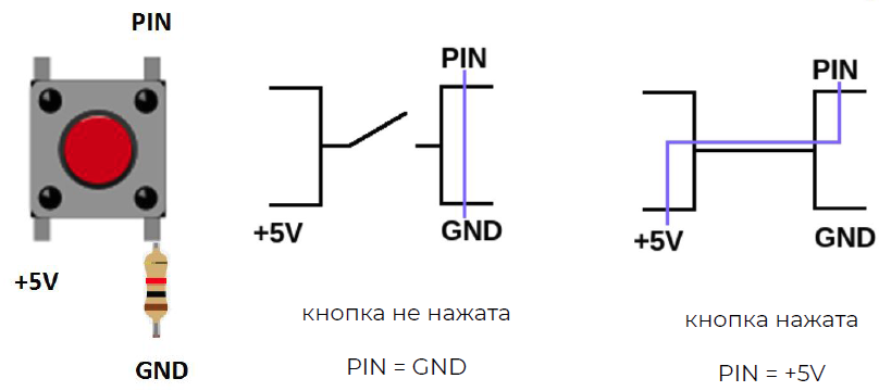
Picture 4. PULL DOWN scheme
The output of the button, which is located opposite the pin from which its state is read, is connected to the power supply or ground necessarily through a resistor. The nominal value of the resistor is 1 kOhm. The resistor helps to avoid interference and reading the wrong state of the button.
Manually operated traffic light
###assembling the circuit Let's assemble a manually operated traffic light. In it, the LEDs will turn on using the buttons. Each traffic light has its own button. We connect the buttons according to the PULL DOWN scheme.
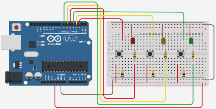
Picture 5. Manual traffic light scheme
Traffic light control software
We will program the manual traffic light. Let's announce the LEDs and buttons. In the procedure void setup() we will configure pins for LEDs and buttons:
- INPUT buttons, read their status;
- LEDs - OUTPUT (OUTPUT) we set their state.
In the procedure void loop() there will be 4 possible options:
- IF the button responsible for turning on the red LED is pressed, then it will turn on;
- IF the button responsible for turning on the yellow LED is pressed, it will turn on;
- IF the button responsible for turning on the green LED is pressed, it will turn on;
- OTHERWISE, all three LEDs will be turned off.
``cpp //creating variables for LEDs int ledRed = 5; int ledYellow = 6; int ledGreen = 7; //creating variables for buttons #define buttonRed 2 #define buttonYellow 3 #define buttonGreen 4
void setup(){ //configuring the pins to which the LEDs are connected as pinMode outputs(ledRed, OUTPUT); pinMode(ledYellow, OUTPUT); pinMode(ledGreen, OUTPUT); //we configure the pins to which the buttons are connected as pinMode inputs(buttonRed, INPUT); pinMode(buttonYellow, INPUT); pinMode(buttonGreen, INPUT); }
void loop(){ //if the button responsible for turning on the red LED is pressed, the red LED turns on if(digitalRead(buttonRed)==HIGH){ digitalWrite(ledRed, HIGH); } //if the button responsible for turning on the yellow LED is pressed, the yellow LED turns on else if(digitalRead(buttonYellow)==HIGH){ digitalWrite(ledYellow, HIGH); } //if the button responsible for turning on the green LED is pressed, the green LED turns on else if(digitalRead(buttonGreen)==HIGH){ digitalWrite(ledGreen, HIGH); } //otherwise all three LEDs are off else{ digitalWrite(ledRed, LOW); digitalWrite(ledYellow, LOW); digitalWrite(ledGreen, LOW); } }
:::tip
More information about **pinMode()** can be read [here](http://arduino.ru/Reference/PinMode "pinMode()").

More information about **if...else** can be read [here](http://arduino.ru/Reference/Else "If-Else").
:::

## Tasks

1. Assemble a circuit from an Arduino, a blue LED connected to pin 11 with a 390 ohm resistor, and a button with a 10 kOhm resistor connected to pin 3. Program the Arduino so that the LED cyclically turns on for 0.3 seconds, and turns off for 0.3 seconds when the button is pressed, and never turns on when released.

2. Assemble a circuit of Arduino, red and blue LEDs connected to pins 8 and 9 with 390 Ohm resistors, and a button with a 10 kOhm resistor connected to pin 4. Program the Arduino so that the LEDs turn on and off alternately for 0.5 seconds in the opposite phase - if the first one is turned on, the second one is turned off and vice versa. The LEDs should turn on alternately after a short single press of the button, and stop turning on after the next short single press of the button.