LED
Assembling the circuit
Create a new project on the Tinkercad platform and add the Arduino board to it, which is located in the Basic Components section.
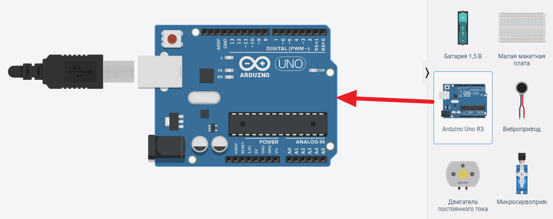
Picture 1. New project
Add a resistor and an LED, assemble a circuit like this.
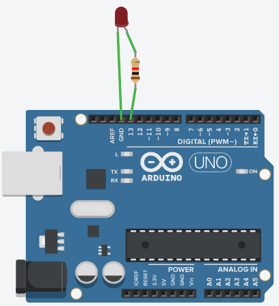
Picture 2. The specified chain
Let's look at the chain and get acquainted with the components:
LED is a semiconductor device that can glow like a small light bulb. One output is the cathode, we connect it to the ground (ground or GND for short), the second output is the anode, we connect it to the voltage source, it can be called the control output, because when voltage is applied to it, then The LED is on. We will supply voltage (control signal) from the Arduino board to this pin.
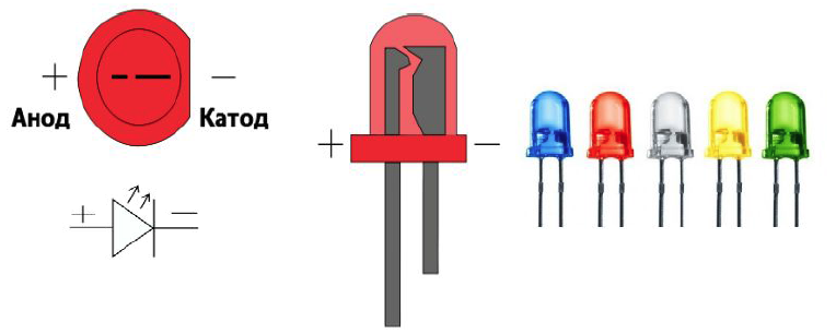
Picture 3. LED
A resistor is a component of an electrical circuit that weakens the current strength. If you do not use a resistor, the LED will quickly fail (burn out) because the current in it will be almost unlimited, it will quickly heat up and melt inside.
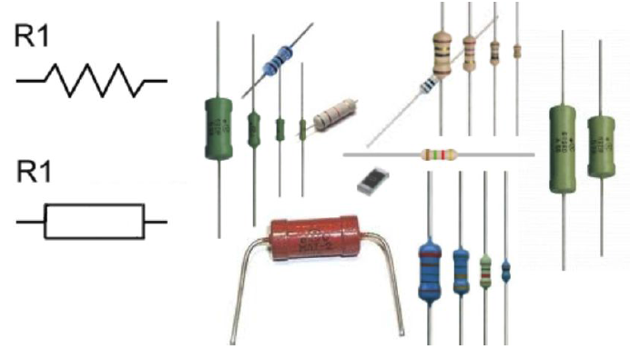
Picture 4. The resistor
All the elements in the diagram are connected to each other and the Arduino board using wires. In order to draw a wire, you need to click the mouse at the first connection point, move it to the end point of the connection and click again. The wire will be conducted directly. Then, for the readability of the circuit, the wires can be bent. You can add a bending point by double-clicking anywhere on the wire, and then pulling on this point to bend the wire. Or, when laying a wire, you can lead it in a straight line, each time clicking the mouse at the point of rotation and the wire will automatically bend. You can also change the colors of the wires in the parameters, thereby creating beautiful diagrams that are readable. If you set the starting point of the wire, and then realized that you made a mistake and the wire needs to be removed, then you need to press the Esc key and the wire will be removed. You can delete an existing wire by selecting it and pressing the Delete key.
You can find out about encoding the values of the resistor using strips [here] (https://www.chipdip.ru/info/rescalc "Encoding of resistor values using strips").
Programming
Enabling Code Mode
The main functions that we will use when writing the program:
- pinMode() - sets the pin for input/output;
- digitalWrite() - supplies voltage to the pin;
- delay() - suspends the program for the duration of the delay.
To program the Arduino, press the Code button. At the first start, blocks appear with which you can also program the Arduino. Switch them to Text.
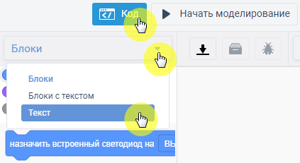
Picture 5. Arduino Programming
The area of programming can be expanded by pulling on its edge.
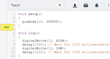
Picture 6. The scope of the program
Any program should contain 2 basic procedures:
- void setup() - ports are being configured;
- void loop() is the main code that runs in an infinite loop.
The first program
Enter the following code:
void setup() {
pinMode(13, OUTPUT);
}

void loop() {
digitalWrite(13, HIGH); // turn on the LED
  delay(1000); // wait 1 second
  digitalWrite(13, LOW); // turn off the LED
  delay(1000); // wait 1 second
}
``

To start the program, click the **Start Simulation** button. While the program is running, you can see the time of its execution. To stop the program execution, click **Stop simulation**.

:::tip
Learn more about **delay()** can be read on [page](http://arduino.ru/Reference/Delay "delay()").

More information about **digitalWrite()** can be found on [page](http://arduino.ru/Reference/DigitalWrite "digitalWrite()").
:::

## Tasks

1. Assemble a circuit from an Arduino, a blue LED connected to pin 10, and a 390 ohm resistor. Program the Arduino to cycle the LED on for 2 seconds, and off for 2 seconds.

2. Assemble a circuit of Arduino, red and blue LEDs connected to pins 8 and 9, and 390 ohm resistors. Program the Arduino so that the LEDs turn on and off alternately for 0.5 seconds in the opposite phase - if the first one is on, then the second one is off and vice versa.