Acquaintance with Arduino
Arduino is an electronic board with a microcontroller for fast development of electronic devices for beginners. The platform is very popular all over the world due to the convenience and simplicity of the programming language. The device is programmed via USB without using programmers. The Arduino board has built-in short circuit protection, which prevents beginners from disabling it.
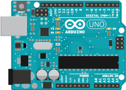
Picture 1. Arduino UNO Board
The Arduino board can be used in conjunction with the Orbicraft designer, expanding its functionality and modeling its own "space missions". The following sections of the Wiki will help beginners to master the programming of this microcontroller. The first steps in working with the Arduino board can be done online, without having it in front of you on the table, using the online platform [TinkerCAD] (https://www.tinkercad.com / "TinkerCAD")

Picture 2. TinkerCAD Online Platform
Registration on the Tinkercad platform
Register on the platform to be able to save all your projects in the cloud and send them to the educational department of Sputnix for verification.
Click on the button Join;

Picture 3. Join
Choose self-registration;

Picture 4. Self-registration
Complete the registration procedure;

Picture 5. Registration procedure
After registering and logging in, switch to the electrical circuits section circuits;

Picture 6. Section of electrical circuits
Press the button Create a chain;

Picture 7. Creation of electrical circuits
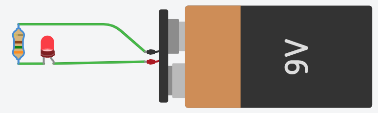
Create the simplest electrical circuit by dragging the necessary components into the simulation area and connect them with conductors as shown in the picture;

Picture 8. The simplest electrical circuit
Run the simulation by clicking on the appropriate button;

Picture 9. Modeling
The platform will simulate the power supply, the flow of electric current and the LED will glow faintly.

Picture 10. Simulation of power supply
Change the nominal value of the resistor by clicking on it.

Picture 11. Changing the value of the resistor
The brightness of the LED will increase.
Picture 12. Increased LED brightness
Please note! The strips on the resistor changed their color when the nominal value was changed. More information about encoding the values of the resistor using strips can be found [here] (https://www.chipdip.ru/info/rescalc "chipdip").
Tasks
Assemble the circuit from a voltage source with a nominal value of 9V, a green LED and two series-connected resistors with a nominal value of 220 ohms each.
Assemble a circuit consisting of three serial voltage sources with a nominal value of 1.5V, a white LED and two parallel connected resistors with a nominal value of 1 kOhm each.