Photoresistor
The principle of operation of the photoresistor
A photoresistor is a semiconductor device whose electrical resistance varies depending on the intensity of the light incident on it. The more intense the light, the lower the resistance of the photoresistor becomes.
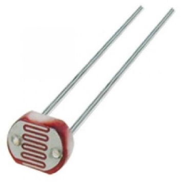
Picture 1. Photoresistor
The photoresistor has two outputs: one is connected to the power supply, the second through a resistor to the ground. A wire is installed at the junction of the photoresistor output with the resistor to read its readings. The nominal value of the resistor is from 1 to 10 kOhms. Depending on the value of the resistor, the range of sensor readings will change.
On the tinkercad platform, you can change the illumination of the resistor by moving the slider from left to right.

Picture 2. Changing the illumination of the resistor
Reading the photoresistor readings into the port monitor
Assembling a circuit with a photoresistor
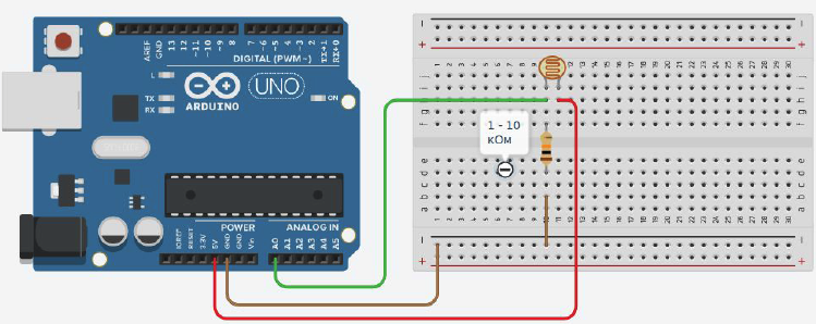
Picture 3. Circuit with photoresistor
Program for reading photoresistor readings into the port monitor
#define photores A0 //creating a variable for
the int light photoresistor; //creating a variable to store the photoresistor readings

void setup(){
pinMode(photores, INPUT); //setting the pin to which the photoresistor is connected as an input
  Serial.begin(9600); //setting up work with the port monitor
}

void loop(){
light = analogRead(photores); // reading the photoresistor readings and saving them to the variable light
Serial.print("Light ="); //output the word "Light:"
Serial to the port monitor.println(light); //output the value of the light variable to the port monitor and wait for half a second
  delay(500);
}
Automatic lighting
Putting together a diagram
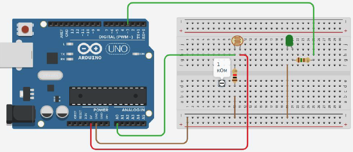
Picture 4. Scheme for automatic lighting
A program for automatically turning on the lighting
#define photores A0 //creating a variable for the photoresistor
#define led 3 //creating a variable for
the int light LED; //creating a variable for storing photoresistor readings
int day = 400; //creating a variable for the day-night(light-dark)

void setup condition(){
pinMode(photores, INPUT); //setting the pin to which the photoresistor is connected as an input
  pinMode(led, OUTPUT); //setting the pin to which the LED is connected as an output
  Serial.begin(9600); // setting up work with the port monitor
}

void loop(){
light = analogRead(photores); //reading the photoresistor readings and saving them to the variable light
Serial.print("Light =");
  Serial.println(light); //output the photoresistor readings to the port monitor
  if(light<day){                 //if the current illumination is less than 400, then turn on the LED
    digitalWrite(led, HIGH);
  }
else{ //otherwise the LED is off
    digitalWrite(led, LOW);
  }
delay(100); //delay of 100 milliseconds
}
We control the speed of the servo motor depending on the illumination
We assemble the circuit
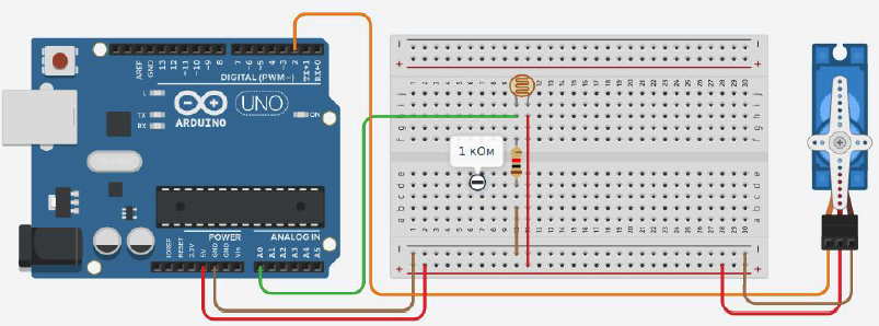
Picture 5. Scheme for automatic lighting
Program for controlling the speed of the servo motor depending on the illumination
#include <Servo.h> //connecting the library to work with the servomotor
#define photores A0 //creating a variable for the photoresistor
Servo myservo; //declare
the int light servomotor; //create a variable to store the readings
of the int msec photoresistor; //create a variable responsible for the speed of the servomotor movements
                          //this variable determines the delay time of the servo motor in each position during its movement
                          //the higher the value of the variable, the slower the servo motor rotates

void setup(){
  pinMode(photores, INPUT); //configure the pin to which the photoresistor is connected as the input
of myservo.attach(2); //configure pin 2 as the control pin of the servo
motor }

void loop(){
for(int i=0; i<=180; i++){ //cycle to rotate the servomotor from 0 to 180
myservo.write(i);
    delay(msec);
    Checklist(); //a function that checks the light level
  }
for(int i=180; i>=0; i--){ //cycle for rotating the servomotor from 180 to 0
myservo.write(i);
    delay(msec);
    Checklist(); //function that checks the light level
}
}

//the function reads the photoresistor readings
//then converts them during the delay of the servo motor in each position
void checkLight(){
  light = analogRead(photores);
  msec = map(light, 6, 679, 100, 5);
}
Tasks
Assemble a circuit with two photoresistors mounted at an angle of 90 degrees relative to each other. Write a program that, after calibration, will determine the direction to the light source in the range of +-90 degrees with an accuracy of 10 degrees.
Assemble a circuit with four photoresistors mounted at an angle of 90 degrees relative to each other. Write a program that, after calibration, will determine the direction to the light source in the range of +-180 degrees with an accuracy of 15 degrees.