Servo motor
Servo motor device
A servo motor is a motor whose shaft position can be controlled. It differs from a conventional motor in that it can be precisely set in degrees to the position in which the shaft will stand. Servos are used to simulate various mechanical movements of robots. There are 2 types of servomotors:
- the shaft rotates 180 degrees;
- The shaft rotates 360 degrees in a circle.
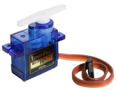
Picture 1. Servomotor
Inside, the servo motor looks like this: the main element is a DC motor, then the gearbox gears, which reduce the speed of rotation of the shaft, the output shaft is the element where the servo nozzle is installed (it will move to a predetermined position). The ability to set the position of the servo motor is provided by a potentiometer and a printed circuit board with control electronics.
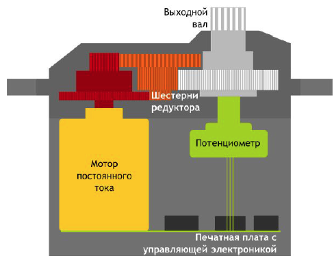
Picture 2. The device of the servo motor
This is what the servomotors in Tinkercad look like.
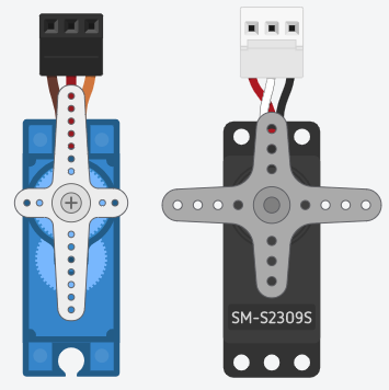
Picture 3. Servomotors in Tinkercad
The servo motor has 3 outputs: it is painted in different colors.
- Red - +5V power supply;
- brown - GND grounding;
- Orange is the control pin, connects to the digital pin of the Arduino.
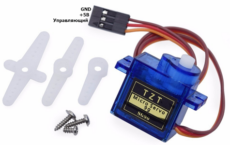
Picture 4. Servo motor outputs
To work with the Arduino servomotor, you need to use the library. A library is a separate file with a set of commands for an element. There are libraries for servomotors, for sensors, for displays, etc.
To connect the library, click on the “Libraries” icon in code mode, then select the desired library from the list. We need the Servo library. Click “enable" and the program will display the line cpp #include <Servo.h>, which means that you can now use the commands of this library in your program.
![Connecting the library]
Picture 5. Connecting the library
To start working with a servomotor, you need to declare it: Servo space and the name of the servomotor. In the example, the name is myservo. The servomotor declaration must be before the procedure ``cpp void setup() ```.
Next, its name is used to send commands to the servomotor. The main commands for working with the servomotor are:
- attach() - indicates which pin the control pin of the servomotor is connected to;
- write() - sets the position of the servomotor. The position is set by a number from 0 to 180;
- read() - reads the current position of the servo motor.
Servo motor control
Putting together a diagram
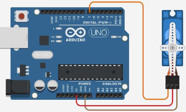
Picture 6. Servo motor control circuit
The program for installing the servo motor in a given position
#include <Servo.h> //connecting the library to work with the servomotor
Servo myservo; //declaring a servomotor
void setup(){
myservo.attach(7); //setting pin 7 as the control pin of the servomotor
}
void loop(){
myservo.write(0); //setting position 0
delay(2000); //waiting for 2 seconds
myservo.write(90); //setting position 90
delay(2000); //waiting for 2 seconds
myservo.write(180); //setting the position 180
delay(2000); //waiting for 2 seconds
}
``
### Smooth rotation of the servo motor in one direction
```cpp
#include <Servo.h> //connecting the library to work with the servomotor
Servo myservo; //declaring a servomotor
void setup(){
myservo.attach(7); //configuring pin 7 as the control pin of the servomotor
}
void loop(){
for(int i=0; i<=180; i++){ //in the cycle, we increase the position of the servo motor from 0 to 180,
myservo.write(i);
delay(50); //lingering in each position for 50 milliseconds
}
}
``
### Smooth rotation of the servo motor in both directions
```cpp
#include <Servo.h> //connecting the library to work with the servomotor
Servo myservo; //declaring a servomotor
void setup(){
myservo.attach(7); //setting pin 7 as the control pin of the servomotor
}
void loop(){
for(int i=0; i<=180; i++){ //in the loop, increase the position of the servomotor from 0 to 180,
myservo.write(i);
delay(50); //lingering in each position for 50 milliseconds
}
for(int i=180; i>=0; i--){ //in the loop, reduce the position of the servo motor from 180 to 0,
myservo.write(i);
delay(50); //lingering in each position for 50 milliseconds
}
}
``
## We control the servo motor using a potentiometer
### Putting together a diagram
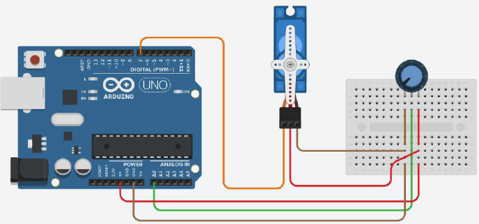
_Picture 7. Control circuit of the servo motor using a potentiometer_
### We control the servo motor using a potentiometer
```cpp
#include <Servo.h> //connecting the library to work with the servomotor
#define potenciometr A0 //creating a variable for the potentiometer
Servo myservo; //declaring the servomotor
int potValue; //creating a variable to store the potentiometer readings
void setup(){
myservo.attach(7); //configuring pin 7 as the control pin of the servomotor
pinMode(potenciometr, INPUT); //setting the pin to which the potentiometer is connected as an input
Serial.begin(9600); // setting up work with the port monitor
}
void loop(){
potValue = analogRead(potenciometr); //reading the potentiometer readings and saving them to the potValue variable
potValue = map(potValue, 0, 1023, 0, 180); // converting the range of values 0-1023 to a new one range 0-180
Serial.println(potValue); //output the value of the potValue variable
myservo.write(potValue) to the port monitor; //set the position of the servomotor to the value of the potValue variable
}
``
### We control the servomotor via the port monitor
```cpp
#include <Servo.h> //connecting the library to work with the servomotor
Servo myservo; //declaring the servomotor
int position; //creating a variable to store the position value for the servomotor
char data; //creating a variable to store commands entered into the serial interface monitor
void setup(){
myservo.attach(7); //configuring pin 7 as the control pin of the servomotor
Serial.begin(9600); //setting up work with the port monitor
}
void loop(){
myservo.write(position); //setting the position of the servomotor equal to the value of the position variable
if(Serial.available()>0){ //check if the commands have been received in the port monitor
data = Serial.read(); //read the received commands
Serial.println(data); //output the received command
if(data == '+') to the port monitor{ //if the received command was '+', then the position variable is incremented by 10,
position = position + 10;
}
else if(data == '-'){ // and if '-', then the position variable is reduced by 10
position = position - 10;
}
myservo.write(position); //setting the position of the servomotor equal to the value of the position variable
Serial.println(position); //output the value of the position variable to the port monitor
}
}
``
You can read more about the **for** cycle [here](http://arduino.ru/Reference/For "FOR loop").
## Tasks
1. Make an analog clock. Assemble the circuit from the Arduino board and the servo motor. Program the Arduino so that the servo motor shaft rotates like a second hand - 6 degrees per second.
2. Assemble the circuit from the Arduino board, servo motor and potentiometer. Program the Arduino so that when the potentiometer is in the central position, the servo motor shaft will also be in the central position. When turning the potentiometer knob to the left to the end, the servo motor shaft should turn by -90 degrees, and when turning the knob to the right by 90 degrees.